Scrap iron cleaning equipment for machining factory

A technology for cleaning equipment and processing plants, applied to cleaning equipment, cleaning machinery, manual sweeping machinery, etc., can solve the problems of low efficiency of iron scrap cleaning, reduced work efficiency, and increased labor intensity of operators, so as to achieve high work efficiency and easy operation. Simple, convenient and efficient cleaning of iron filings

Active Publication Date: 2021-06-11
郑金源
View PDF7 Cites 0 Cited by
  • Summary
  • Abstract
  • Description
  • Claims
  • Application Information

AI Technical Summary

Problems solved by technology

This method not only increases the labor intensity of the operator, but also reduces the work efficiency, and at the same time, the efficiency of cleaning iron filings is low

Method used


Image

  • Scrap iron cleaning equipment for machining factory
  • Scrap iron cleaning equipment for machining factory
  • Scrap iron cleaning equipment for machining factory

Examples


Embodiment 1

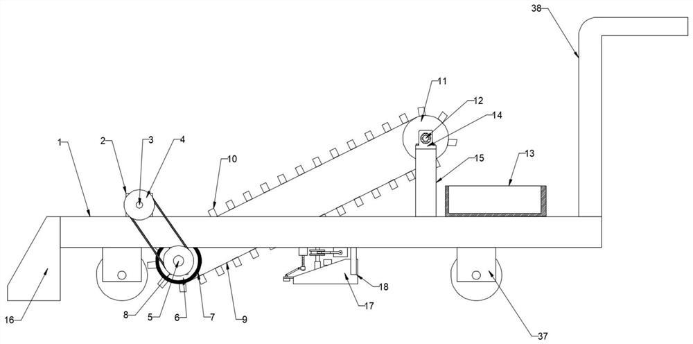
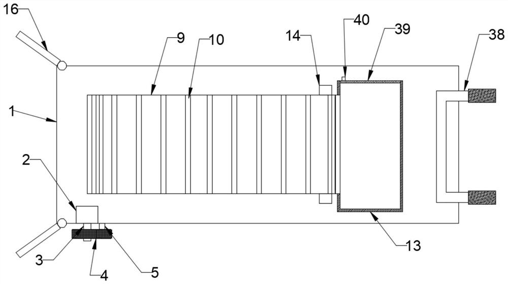
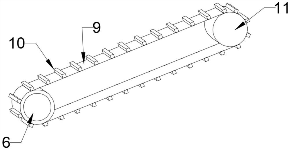
[0026] see Figure 1~4 , in an embodiment of the present invention, a scrap iron chip cleaning device used in a mechanical processing plant includes a base 1, the base 1 is provided with a primary cleaning mechanism, the primary cleaning mechanism includes a first motor 2, and the first A motor 2 is provided with a first transmission shaft 3, the lower part of the first transmission shaft 3 is provided with a first driven shaft 5, and the first driven shaft 5 is connected to the lower end surface of the base 1 through a first mounting plate 8, The first driven shaft 5 is provided with a main drive roller 6, and the first driven shaft 3 and the first driven shaft 5 are respectively provided with a pulley 4, and the two pulleys 4 are connected by a belt, so The main drive roller 6 is sleeved with an annular magnet 7, and one side of the first driven shaft 5 is provided with a second driven shaft 12, and the second driven shaft 12 is provided with a driven roller 11, and the driv...

Embodiment 2

[0028] see Figure 5The difference between this embodiment of the present invention and Embodiment 1 is that a secondary cleaning mechanism is provided on the lower end surface of the base 1, and the secondary cleaning mechanism includes a second collection frame 17, a second motor 19 and a third motor 20 , the second collection frame 17 is provided with a third mounting plate 18, and the upper end of the third mounting plate 18 is fixedly connected with the base 1, the second motor 19 is provided with a second transmission shaft 21, and the second transmission The shaft 21 is provided with a toggle block 23, and one side of the second motor 19 is provided with a connecting shaft 24, and the upper end of the connecting shaft 24 is fixedly connected with the lower end surface of the base 1, and the connecting shaft 24 is provided with a sliding sleeve 26 , the upper part of the sliding sleeve 26 is provided with a toggle wheel 25, and the toggle wheel 25 is provided with a groo...


PUM


Abstract

The invention discloses scrap iron cleaning equipment for a machining factory, relates to the technical field of machining, and mainly aims to solve the problems that the labor intensity of operators is increased, the working efficiency is reduced and the scrap iron cleaning efficiency is relatively low as scrap iron splashed to the ground is treated by mostly adopting a manual cleaning mode in the machining factory. The scrap iron cleaning equipment for the machining factory comprises a base, the base is provided with a first-stage cleaning mechanism, the first-stage cleaning mechanism comprises a first motor, the first motor is provided with a first transmission shaft, the lower portion of the first transmission shaft is provided with a first driven shaft, and the first driven shaft is provided with a main transmission roller; and the main transmission roller is sleeved with an annular magnet, the first driven shaft is provided with a driven roller, the conveying belt is provided with a check block, and a first collecting frame is arranged on the upper end face of the base. The equipment can achieve automatic cleaning of scrap iron on the ground, manual cleaning is not needed, operation is easy, and the working efficiency is high.

Description

technical field [0001] The invention relates to the technical field of mechanical processing, in particular to a scrap iron scrap cleaning device used in a mechanical processing plant. Background technique [0002] Machining refers to the whole process of using mechanical processing to make the shape, size, relative position and properties of the blank into qualified parts according to the drawing and size. The processing technology is the work that the craftsmen need to do before processing, to avoid Processing errors occur during processing, resulting in economic losses. [0003] A large amount of iron filings are often produced during the machining process, and iron filings will inevitably splash on the ground in the working area. If they are not cleaned up in time, the working environment of the operator will be deteriorated. At the same time, the accumulation of iron filings on the ground is dangerous. Hidden danger. Existing machining factories mostly use manual clea...

Claims


Application Information

Patent Timeline
IPC IPC(8): A47L11/24A47L11/40
CPCA47L11/24A47L11/4036A47L11/4069A47L11/4013A47L11/40
Inventor 郑金源
Owner 郑金源
Why Eureka
Try Eureka