Thrombus prevention device
A thrombus and rotary shaft technology, applied in friction resistance devices, training equipment for regulating cardiovascular system, sports accessories, etc. Easy to arterial ischemia or venous blood return, promote blood flow, good stability
- Summary
- Abstract
- Description
- Claims
- Application Information
AI Technical Summary
Problems solved by technology
Method used
Image
Examples
Embodiment 1
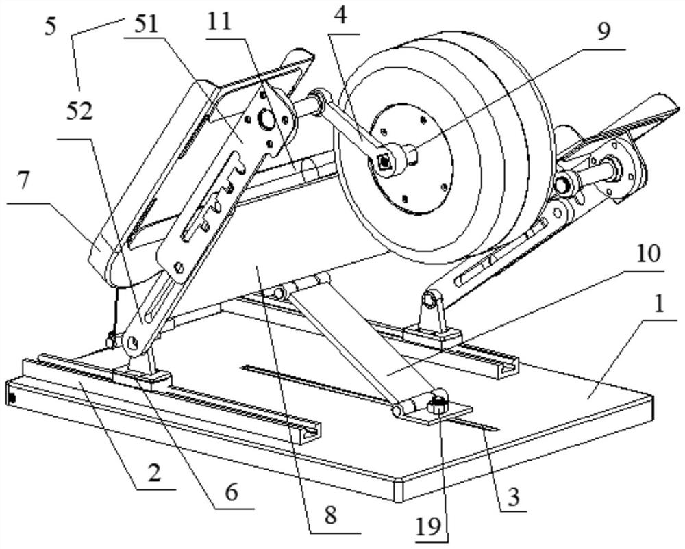
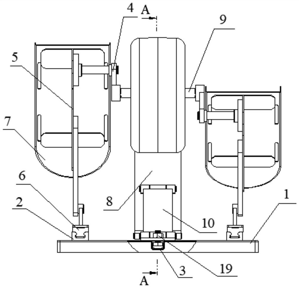
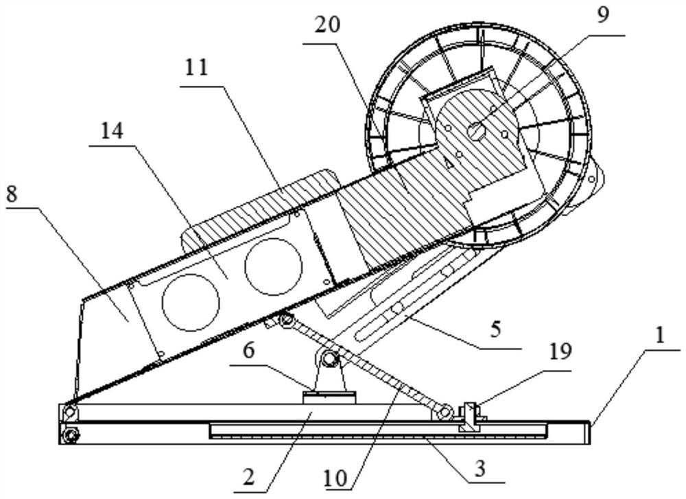
[0099] see Figure 1-6 As shown, this embodiment introduces a thrombosis prevention device that can significantly activate the muscles of the lower limbs of the human body to promote blood flow, and does not interfere with the normal state of muscles and pulses. , The thrombosis prevention device includes a base, a rotating shaft support component, a crank slider mechanism, a pedal and an adjustment mechanism (including the first adjustment mechanism 10 and / or the second adjustment mechanism 13). in, figure 1 A schematic diagram of a three-dimensional structure of a thromboprophylaxis device provided in this embodiment; figure 2 A side view of a thromboprophylaxis device provided in this embodiment; image 3 for along figure 2 The cross-sectional view of A-A direction in the middle; Figure 4 A schematic diagram of the three-dimensional structure of a thrombosis prevention device provided in this embodiment when the bottom plate 12 and the base 1 form a certain angle; ...
Embodiment 2
[0117] Figure 7 with Figure 8 Another thromboprophylaxis device is shown. Compared with the thrombosis prevention device in Embodiment 1, the difference is that the height adjustment positioning groove 3 on the base 1 in Embodiment 1 is replaced by several height adjustment positioning holes 3' arranged at intervals along the length direction of the base 1, and other The structure is similar, so the description will not be repeated. In this embodiment, the supporting plate structure also includes a first supporting plate and a top fixing plate and a bottom fixing plate hinged at both ends of the first supporting plate, and the top fixing plate may be fixed to the In the middle part of the bottom surface of the box body 8 of the rotary shaft supporting part, the bottom fixing plate is connected with any height adjustment positioning hole 3' on the base 1 through bolt and nut fasteners 19, and the height adjustment positioning hole 3' is connected with The support plate str...
Embodiment 3
[0119] Figure 9 A third thromboprophylaxis device of the present invention is shown. Compared with the thrombosis prevention device in Embodiment 1, the difference is that the first adjusting mechanism 10 in Embodiment 1 is replaced by an electric push rod mechanism 10', and other structures are basically the same, so the description will not be repeated.
[0120] Such as Figure 9 As shown, in this embodiment, the electric push rod mechanism 10' includes a drive motor 101 and a push rod 102, the drive motor 101 can be installed on the surface near the right end of the base 1, and the push rod 102 Installed obliquely on the drive motor 101, the free end of the push rod 102 is installed in the middle of the bottom surface of the box body 8, so that the drive motor 101 can push the push rod 102 to move to adjust the distance between the box body 8 and the base 1 angle, in order to achieve the purpose of adjusting the distance between the crank shaft 9 and the base 1 of the ba...
PUM
 Abstract
Description
Claims
Application Information
 - R&D Engineer
- R&D Manager
- IP Professional
- Industry Leading Data Capabilities
- Powerful AI technology
- Patent DNA Extraction
Browse by: Latest US Patents, China's latest patents, Technical Efficacy Thesaurus, Application Domain, Technology Topic, Popular Technical Reports.
© 2024 PatSnap. All rights reserved.Legal|Privacy policy|Modern Slavery Act Transparency Statement|Sitemap|About US| Contact US: help@patsnap.com


