

Spray booth waste gas treatment method
A technology for waste gas treatment and paint spraying room, applied in gas treatment, separation methods, chemical instruments and methods, etc., can solve the problems of high cost and poor treatment effect, and achieve the effect of improving adsorption capacity and good heat exchange effect.
- Summary
- Abstract
- Description
- Claims
- Application Information
AI Technical Summary
Problems solved by technology
Method used
Image

Examples
Embodiment 1
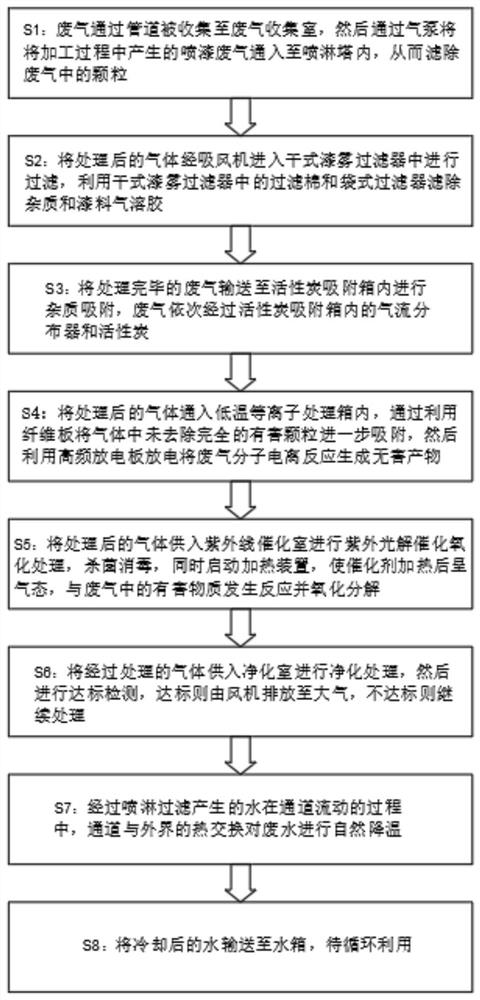
[0027] A method for treating waste gas in a spray booth, comprising the following steps:
[0028] Step 1: The waste gas is collected into the waste gas collection chamber through the pipeline, and then the spray paint waste gas generated during the processing is passed into the spray tower through the air pump, so as to filter out the particles in the waste gas;
[0029] Step 2: Filter the treated gas into the dry paint mist filter through the suction fan, and use the filter cotton and bag filter in the dry paint mist filter to filter out impurities and paint aerosols;
[0030] Step 3: Transport the treated exhaust gas to the activated carbon adsorption box for impurity adsorption, and the exhaust gas passes through the air distributor and activated carbon in the activated carbon adsorption box in turn;
[0031] Step 4: Pass the treated gas into the low-temperature plasma treatment box, further absorb the incompletely removed harmful particles in the gas by using fiberboard, a...
Embodiment 2
[0045] A method for treating waste gas in a spray booth, comprising the following steps:
[0046] Step 1: The waste gas is collected into the waste gas collection chamber through the pipeline, and then the spray paint waste gas generated during the processing is passed into the spray tower through the air pump, so as to filter out the particles in the waste gas;
[0047] Step 2: Filter the treated gas into the dry paint mist filter through the suction fan, and use the filter cotton and bag filter in the dry paint mist filter to filter out impurities and paint aerosols;
[0048] Step 3: Transport the treated exhaust gas to the activated carbon adsorption box for impurity adsorption, and the exhaust gas passes through the air distributor and activated carbon in the activated carbon adsorption box in turn;
[0049] Step 4: Pass the treated gas into the low-temperature plasma treatment box, further absorb the incompletely removed harmful particles in the gas by using fiberboard, a...
PUM
 Abstract
Description
Claims
Application Information