Magnetic digital microfluidic chip and loading structure thereof

A digital microfluidic and chip technology, applied in fluid controllers, laboratory equipment, laboratory containers, etc., can solve the problems of inconvenient transfer of liquid droplets, inconvenient separation of magnetic particles and liquid droplets, and poor usability. Good protection and storage effect

Active Publication Date: 2021-06-11
CHINA-SINGAPORE INT JOINT RES INST
View PDF8 Cites 0 Cited by
  • Summary
  • Abstract
  • Description
  • Claims
  • Application Information

AI Technical Summary

Problems solved by technology

[0008] The purpose of the present invention is to overcome the above-mentioned defects in the prior art, and provide a magnetic digital microfluidic chip and its loading structure, which solves the problem of existing magnetic digital microflu

Method used


Image

  • Magnetic digital microfluidic chip and loading structure thereof
  • Magnetic digital microfluidic chip and loading structure thereof
  • Magnetic digital microfluidic chip and loading structure thereof

Examples


Embodiment 1

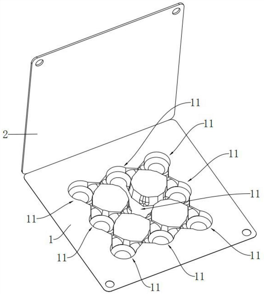
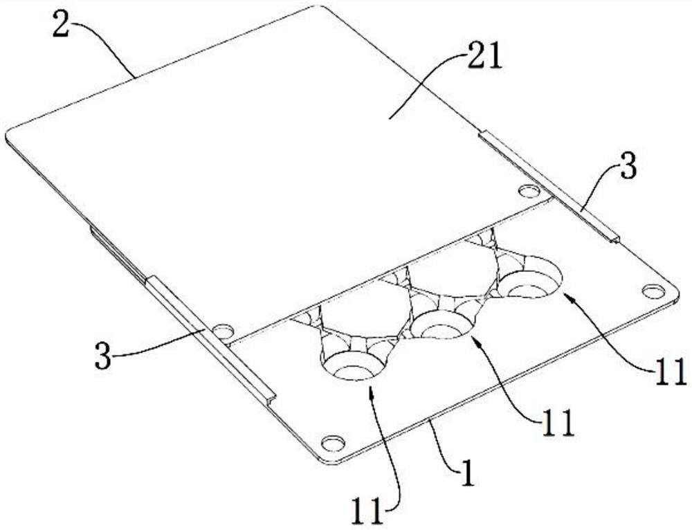
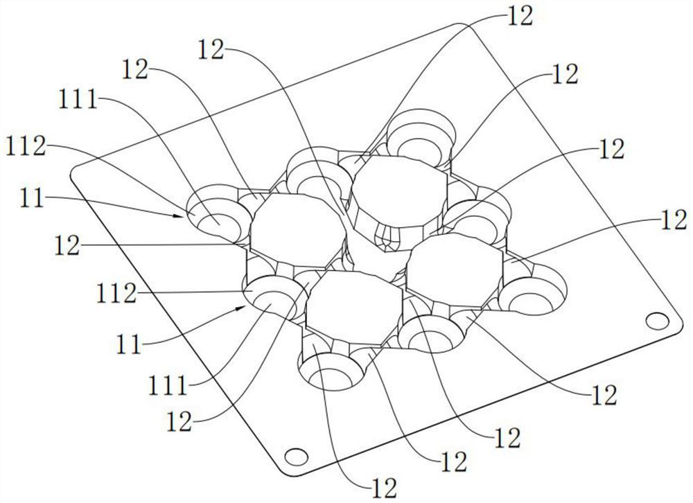
[0034] Such as Figure 1-Figure 3 As shown, the present invention provides a magnetic digital microfluidic chip, which is PVC (polyvinyl chloride), PC (polycarbonate), PP (polypropylene), PET (polyethylene terephthalate), Quartz or metal materials, but the material of this chip is not limited to the above materials, it can be processed by blister technology, injection molding process, computer numerical control machine tool (CNC) processing, hot pressing process, 3D printing, etc., but the chip’s The processing is not limited to the above-mentioned processing methods, and the material is preferably PET (polyethylene terephthalate) in this embodiment.

[0035] Specifically, the magnetic digital microfluidic chip includes a chip base plate 1 and a chip cover plate 2 . Wherein, the end surface of the chip bottom plate 1 facing the chip cover plate 2 is provided with several droplet chambers 11 distributed in a regular or irregular array and opening above. In this embodiment, the...

Embodiment 2

[0041] Such as Figure 4 and Figure 5 As shown, the present invention also provides a magnetic digital microfluidic chip loading structure, which includes the adapter 4 and the magnetic digital microfluidic chip 5 described in the first embodiment.

[0042] Wherein the adapter 4 includes an upper cover plate 41 and a lower cover plate 42, the middle part of the lower cover plate 42 is provided with a chip receiving groove 421 adapted to the shape of the magnetic digital microfluidic chip 5, and the lower cover plate 42 is used to place the magnetic The digital microfluidic chip 5 is fixed in the chip containing groove 421 . For example, one end of the upper cover 41 is hinged to one end of the lower cover 42 to form an openable structure. Specifically, when storing, the magnetic digital microfluidic chip 5 can be placed in the chip receiving groove 421 of the lower cover 42, and then the upper cover 41 and the lower cover 42 can be closed mutually. By using the adapter 4, n...


PUM


Abstract

The invention discloses a magnetic digital microfluid chip, which relates to the field of magnetic digital microfluid and comprises a chip bottom plate and a chip cover plate, a plurality of liquid drop chambers with openings in the upper parts are arranged on the chip bottom plate; a magnetic flow channel for communicating two adjacent liquid drop chambers can be arranged between every two adjacent liquid drop chambers; the liquid drop chamber comprises a chamber bottom and a chamber wall which is obliquely or vertically arranged on the periphery of the chamber bottom and used for limiting flowing of liquid drops; the chip cover plate is used for covering the upper openings of the plurality of liquid drop chambers; an area of the cover plate part above the droplet chamber can be opened so as to add liquid; the upper end face, back on to the chip bottom plate, of the chip cover plate is a binding face where the magnet moves. The invention also discloses a loading structure of the magnetic digital microfluidic chip. The technical problems that existing liquid drops containing magnetic digital microfluid are prone to evaporation and pollution, the liquid drops are inconvenient to transfer or mix with other liquid drops, magnetic particles and the liquid drops are inconvenient to separate, and usability is poor are solved.

Description

technical field [0001] The invention relates to the technical field of magnetic digital microfluidics, in particular to a magnetic digital microfluidic chip and its loading structure. Background technique [0002] Magnetic digital microfluidics is a type of digital microfluidics. Unlike traditional microfluidics, where objects or reactants are continuous fluids, in magnetic digital microfluidics, reactants exist in the form of individual discrete droplets. It uses magnetic force as a droplet The driving force of the movement relies on the mutual cooperation between the magnetic particles and the peripheral control magnet to control the droplet on the open surface. When the droplet needs to be controlled, the external magnet is placed above or below the chip, and the external magnet Attract the magnetic particles located in the droplet to move. The existence of the surface tension of the liquid prevents the magnetic particles from breaking through the surface of the liquid. O...

Claims


Application Information

Patent Timeline
IPC IPC(8): B01L3/00
CPCB01L3/50273B01L2400/043
Inventor 张翼胡旭洋
Owner CHINA-SINGAPORE INT JOINT RES INST
Why Eureka
Try Eureka