Plane grinding device for measuring grinding pressure in real time and pressure regulation and control method thereof
A real-time measurement and surface grinding technology, which is applied in the field of grinding processing, can solve the problems of difficult control of processing accuracy, large differences in surface roughness values, lack of real-time measurement of grinding force processing devices for surface grinding of large-scale parts, etc. Achieve the effect of preventing the deformation of the process system and improving the precision of surface grinding
- Summary
- Abstract
- Description
- Claims
- Application Information
AI Technical Summary
Problems solved by technology
Method used
Image

Examples
Embodiment 1
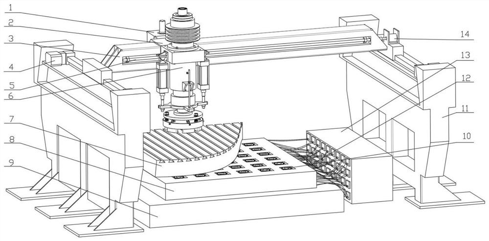
[0036] Such as figure 1 As shown, a surface grinding device for real-time measurement of grinding pressure, including: longitudinal movement structure, lateral movement structure, grinding structure and real-time measurement structure;
[0037] The longitudinal movement structure comprises crossbeam 3, slide rail motor 4 and machine frame 11, and slide rail motor 4 is fixedly installed in the top groove of machine frame 11 by support block, and the sliding block side wall of slide rail motor 4 is fixedly connected with The driving direction of the beam 3 and the slide rail motor 4 on the left and right sides is the same;
[0038] The lateral movement structure includes the lateral movement sleeve 2, the screw rod 5 and the screw motor 14. The sliding block of the slide rail motor 4 on the right is fixedly installed with the screw motor 14 through the mounting frame. The inner wall of the beam 3 is provided with a groove, and the beam The side wall of the groove of 3 is rotati...
Embodiment 2
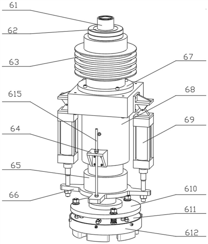
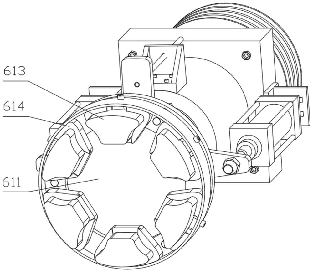
[0043] Such as Figure 2-3 As shown, the grinding head 6 includes a grinding head main shaft 61, a spline sleeve 62, a motor pulley 63, a flange 67, a grinding head frame 68, a hydraulic cylinder 69, a stud connecting block 64, a sleeve 65, and a hydraulic cylinder connecting plate 66. Grinding head spindle connecting plate 610, grinding wheel connecting plate 611, baffle plate 612, grinding wheel 613, grinding wheel fixing block 614 and stud 615, the top of grinding head spindle 61 is fixedly connected with spline sleeve 62, grinding head spindle 61 The spline sleeve 62 is fixedly connected with a motor pulley 63, the bottom of the motor pulley 63 is fixedly connected with a flange 67, the bottom of the flange 67 is fixedly connected with a grinding head frame 68, and both ends of the grinding head frame 68 are fixed. A hydraulic cylinder 69 is connected, the bottom of the telescopic end of the hydraulic cylinder 69 is fixedly connected with a hydraulic cylinder connecting pl...
Embodiment 3
[0045] Such as Figure 4-6 As shown, the dynamometer 10 is two groups of the same Y0° type unit crystal group 101, one group of Y0° type unit crystal group 101 measures the lateral load, the other group of Y0° type unit crystal group 101 measures the longitudinal load, and the Y0° type unit crystal group 101 measures the longitudinal load. The unit crystal group 101 includes two groups of identical Y0° type quartz wafers 1011 and a group of metal electrode sheets 1012, Y0° type quartz wafers 1011 are assembled in pairs, and the metal electrode sheets 1012 are located between the Y0° type quartz wafers 1011, Y0° Type quartz wafer 1011 is installed in the same direction of rotation, the maximum sensitivity direction X axis of Y0 ° type quartz wafer 1011 is on a straight line and the direction differs by 180 °, the maximum sensitivity direction of Y0 ° type unit crystal group 101 is 90 ° right angle, The gap of the dynamometer 10 is filled with high-resistance insulating glue, an...
PUM
 Abstract
Description
Claims
Application Information
 - R&D
- Intellectual Property
- Life Sciences
- Materials
- Tech Scout
- Unparalleled Data Quality
- Higher Quality Content
- 60% Fewer Hallucinations
Browse by: Latest US Patents, China's latest patents, Technical Efficacy Thesaurus, Application Domain, Technology Topic, Popular Technical Reports.
© 2025 PatSnap. All rights reserved.Legal|Privacy policy|Modern Slavery Act Transparency Statement|Sitemap|About US| Contact US: help@patsnap.com