
Method and device for multi-wire cutting of crystal bar

A multi-wire cutting and crystal rod technology, which is applied to fine working devices, manufacturing tools, stone processing equipment, etc., can solve problems such as narrowing of the saw edge, increased sawing path, and inability to effectively discharge heat, so as to avoid wire breakage. , The effect of preventing warpage

Active Publication Date: 2021-06-11
XIAN ESWIN MATERIAL TECH CO LTD +1
View PDF5 Cites 0 Cited by
  • Summary
  • Abstract
  • Description
  • Claims
  • Application Information

AI Technical Summary

Problems solved by technology

[0003] As the size of the wafer increases and the diameter of the cutting wire decreases, the sawing path increases and the saw kerf becomes narrower during the multi-wire cutting process, and the sawdust (silicon powder) is also difficult to remove, resulting in mortar It is difficult to enter the dicing groove, resulting in the heat generated during the multi-wire dicing process cannot be effectively discharged, resulting in local overheating of the wafer and warping, and even wire breakage

Method used


Image

  • Method and device for multi-wire cutting of crystal bar
  • Method and device for multi-wire cutting of crystal bar
  • Method and device for multi-wire cutting of crystal bar

Examples


Embodiment Construction

[0025] The following will clearly and completely describe the technical solutions in the embodiments of the present invention with reference to the drawings in the embodiments of the present invention.

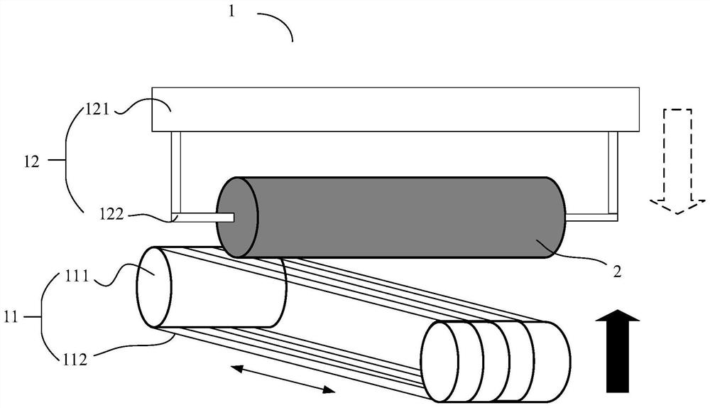
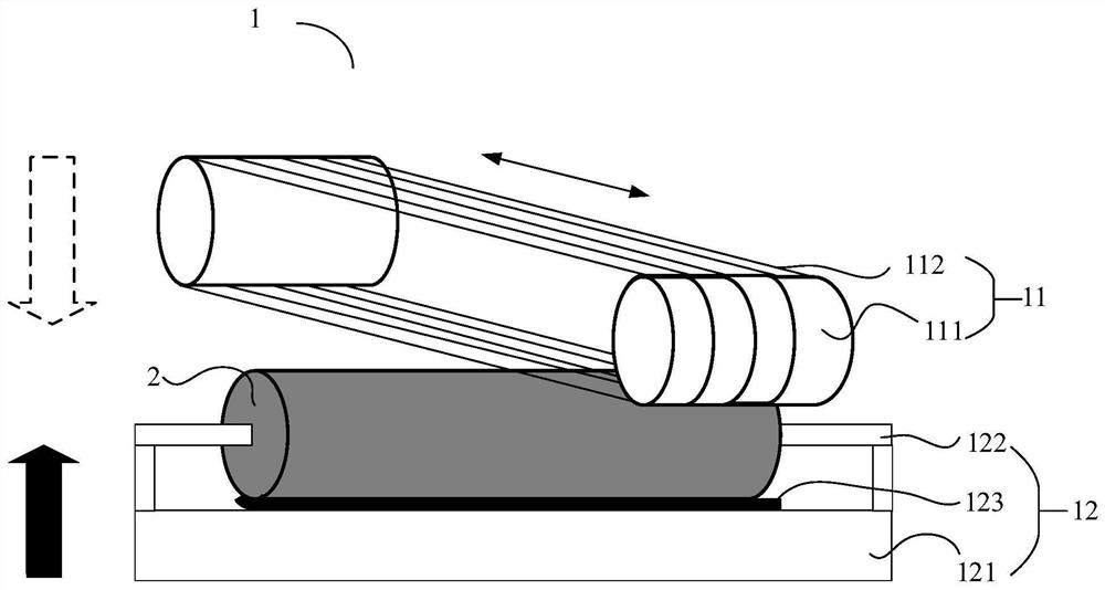
[0026] Referring to FIG. 1, it shows a schematic diagram of the composition of a multi-wire cutting device 1 involved in a conventional solution. It can be understood that the structure shown in FIG. In the implementation state, components are added or subtracted from the composition structure shown in FIG. 1 , which is not specifically limited in this embodiment of the present invention. As shown in FIG. 1 , the multi-wire cutting device 1 may include a cutting part 11 and a mounting part 12; the cutting part 11 may be placed below the vertical direction of the mounting part 12 as shown in FIG. 1( a) in some examples, It can also be placed above the vertical direction of the mounting part 12 as shown in FIG. 1( b ) in some examples. Specifically, the cutting unit 11 may incl...


PUM


Abstract

The embodiment of the invention discloses a method and device for multi-wire cutting of a crystal bar. The method can comprise the steps that on the basis of opposite movement between the to-be-machined crystal bar and a cutting line in high-speed reciprocating motion in the vertical direction, the cutting line makes contact with the to-be-machined crystal bar, and the to-be-machined crystal bar is cut; and in the process that the to-be-machined crystal bar is cut by the cutting line, the to-be-machined crystal bar is controlled to rotate around the axis according to a set rotation strategy.

Description

technical field [0001] Embodiments of the present invention relate to the technical field of wafer processing, and in particular to a method and device for multi-wire cutting crystal ingots. Background technique [0002] Multi-wire cutting technology is currently an advanced slicing processing technology. Its principle is that the cutting wire passes through a set of grooved wheels to form a steel wire mesh with different pitches, and uses the high-speed reciprocating motion of the cutting wire to bring the abrasive into the material to be cut (such as silicon rods). The processing area is ground, and the workpiece to be cut is fed vertically through the lifting of the worktable, so that the workpiece is simultaneously cut into several slices (such as wafers) of required size and shape. Generally, the abrasive used in the multi-wire cutting process is preferably mortar, which can not only help grinding, but also play a cooling role in the multi-wire cutting process. [0003...

Claims


Application Information

Patent Timeline
Patent Type & Authority Applications(China)
IPC IPC(8): B28D5/04B28D7/04B28D7/02B28D7/00
CPCB28D5/042B28D5/0064B28D5/0082B28D5/0076B28D5/007B28D5/0058
Inventor 孙介楠
Owner XIAN ESWIN MATERIAL TECH CO LTD
Learn More