Antibacterial garment cloth preparation system and preparation process

A technology for preparing systems and fabrics, which is applied in the processing of textile material equipment configuration, textile processing machine accessories, textile material processing, etc., can solve the problems of poor durability and easy falling off, and achieve the effect of good durability.

Inactive Publication Date: 2021-06-11
孙百星
View PDF0 Cites 5 Cited by
  • Summary
  • Abstract
  • Description
  • Claims
  • Application Information

AI Technical Summary

Problems solved by technology

However, since the antibacterial agent is only covered on the surface of the ...

Method used


Image

  • Antibacterial garment cloth preparation system and preparation process
  • Antibacterial garment cloth preparation system and preparation process
  • Antibacterial garment cloth preparation system and preparation process

Examples


specific Embodiment approach 1

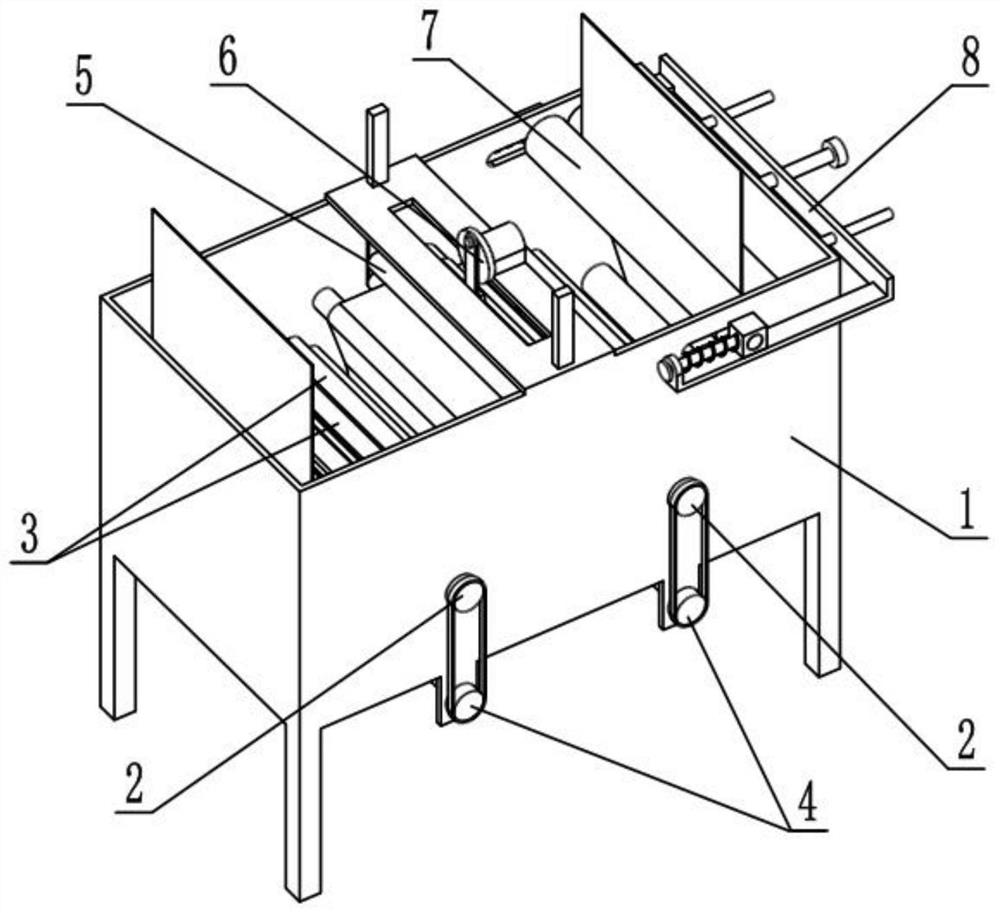
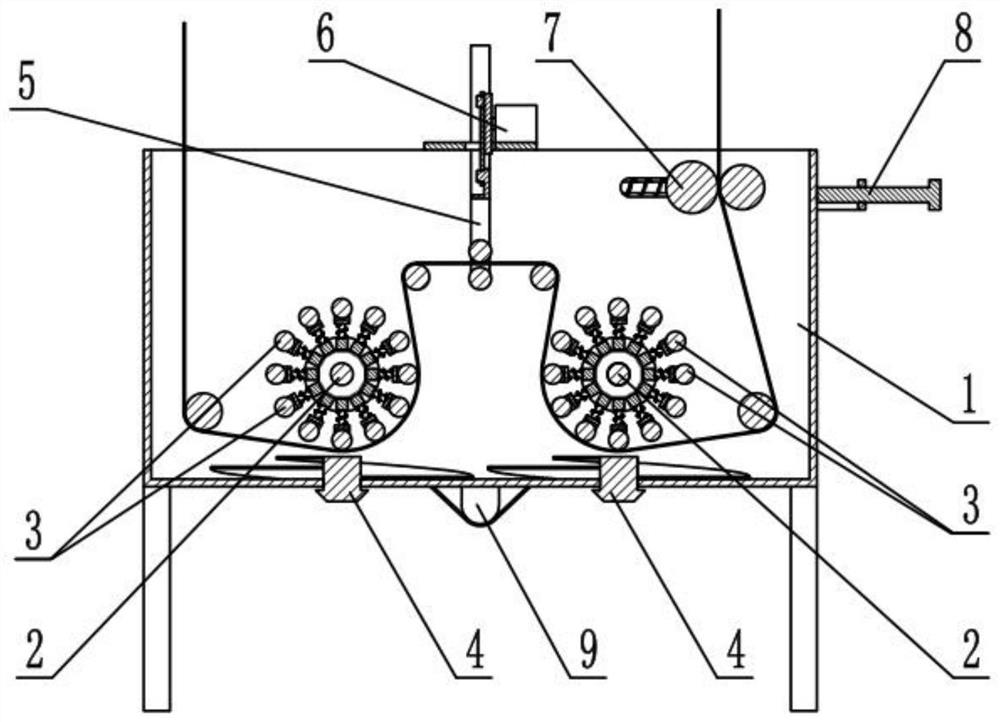
[0034] Such as Figure 1-10 As shown, a clothing antibacterial cloth preparation system includes a soaking box frame 1, a rotating mechanism 2, a cloth beating mechanism 3, a liquid stirring mechanism 4, a vibration mechanism 5, a vibration power mechanism 6, a clamping and dehydrating mechanism 7, and a clamping adjustment mechanism. Mechanism 8 and motor 9, described rotating mechanism 2 is provided with two, and two rotating mechanisms 2 are all rotatably connected in the soaking case frame 1, and are all connected with a plurality of cloth hitting mechanism 3 on two rotating mechanisms 2, so The liquid stirring mechanism 4 is provided with two, and the two liquid stirring mechanisms 4 are all rotatably connected to the lower end of the soaking box frame 1, and the two liquid stirring mechanisms 4 are respectively located directly below the two rotating mechanisms 2, and the two liquid stirring mechanisms 4 are respectively connected to the transmission of the two rotating ...

specific Embodiment approach 2

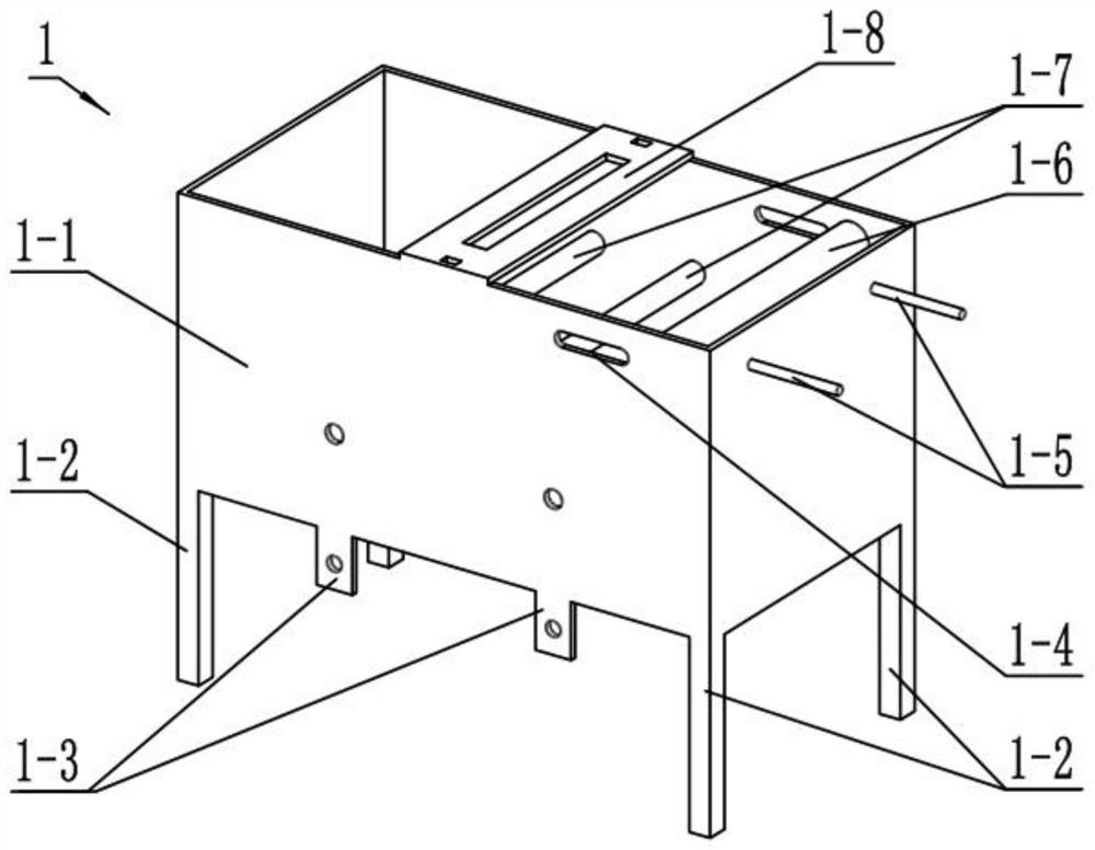
[0037] Such as Figure 1-10 As shown, the soaking box frame 1 includes a box body 1-1, supporting legs 1-2, mounting plate 1-3, sliding slot 1-4, fixed sliding column 1-5, dehydration fixed roller 1-6, Go up block roller 1-7, upper cross plate 1-8 and lower block roller 1-9, the four corners of box body 1-1 lower end are all fixedly connected with supporting leg 1-2, and the lower end of box body 1-1 all There are two mounting plates 1-3 fixedly connected, a long sliding hole 1-4 runs through the box body 1-1, two fixed sliding columns 1-5 are fixedly connected on the right side of the box body 1-1, and the dehydration fixed roller 1-6 is rotatably connected in the box body 1-1 and is located on the right side of the sliding long hole 1-4. There are two upper blocking rollers 1-7, and the two upper blocking rollers 1-7 are rotatably connected to the box body In the middle of 1-1, there are two lower blocking rollers 1-9, the two lower blocking rollers 1-9 are rotatably connec...

specific Embodiment approach 3

[0040] Such as Figure 1-10 As shown, the rotating mechanism 2 includes a rotating shaft 2-1, a rotating side plate 2-2 and a linkage cross bar 2-3, and both ends of the rotating shaft 2-1 are fixedly connected with a rotating side plate 2-2, A plurality of interlocking horizontal bars 2-3 are evenly and fixedly connected in the circumferential direction between the two rotating side plates 2-2, and there are two rotating mechanisms 2, and the two rotating shafts 2-1 are connected to the box Inside the body 1-1, the motor 9 is fixedly connected to the lower end of the box body 1-1, the two rotating shafts 2-1 are located between the two lower blocking rollers 1-9, and the two upper blocking rollers 1-7 are located Between the two rotating shafts 2-1, the motor 9 is connected to the two rotating shafts 2-1 simultaneously.


PUM


Abstract

The invention relates to the field of cloth preparation, in particular to an antibacterial garment cloth preparation system and preparation process. The process comprises the following steps of 1, enabling cloth to pass through a device, immersing the formed cloth into antibacterial agent liquid, continuously immersing the cloth into the antibacterial agent liquid, and pulling out the cloth; 2, starting a motor to drive a cloth beating mechanism to beat the cloth, so that an antibacterial agent can be fully blended into the cloth; 3, driving stirring blades to stir the antibacterial agent liquid while two rotating shafts rotate, and pushing the antibacterial agent liquid to the beaten cloth at the same time; 4, starting a vibration motor to drive two vibration rollers to drive the cloth to vibrate, so that the cloth is switched between a tensioned state and a relaxed state back and forth, and the efficiency that the antibacterial agent is fully blended into the cloth is further improved; and 5, rotating an adjusting bolt, and driving a moving frame to move rightwards in a threaded manner, so that the force of abutting against a dewatering fixed roller by a clamping roller is increased, and the cloth is rapidly dewatered.

Description

technical field [0001] The invention relates to the field of cloth preparation, in particular to a clothing antibacterial cloth preparation system and a preparation process. Background technique [0002] Due to the diversity of the fabric structure, dirt, sweat, etc. are easily deposited on the fabric tissue, and various bacteria and microorganisms are easy to breed. If these harmful bacteria cannot be eliminated, various diseases will occur and endanger the health of the wearer. In order to make the cloth antibacterial, two methods of antibacterial fiber or fabric finishing are usually used to carry out antibacterial treatment on the cloth. The fabric post-finishing method is to process and arrange non-antibacterial fabrics in the later stage. Generally, the finishing agent and antibacterial agent are mixed and covered on the surface of the fabric. This method is low in cost and easy to operate. However, since the antibacterial agent is only covered on the surface of the...

Claims


Application Information

Patent Timeline
IPC IPC(8): D06B3/20D06B3/34D06B23/20D06B15/02
CPCD06B3/206D06B3/34D06B15/02D06B23/205
Inventor 孙百星
Owner 孙百星
Why Eureka
Try Eureka