
Manufacturing method of test block forultrasonic detection of non-welding defect of diffusion welding interface

A production method and ultrasonic detection technology, which are applied in the preparation of test samples and the analysis of solids using sound waves/ultrasonic waves/infrasonic waves, etc., can solve problems such as difficult identification, difficult identification of ultrasonic reflected waves, and inaccurate ultrasonic reflected waves, and achieve easy recognition effect

Pending Publication Date: 2021-06-11
AVIC LIYUAN HYDRAULIC
View PDF0 Cites 0 Cited by
  • Summary
  • Abstract
  • Description
  • Claims
  • Application Information

AI Technical Summary

Problems solved by technology

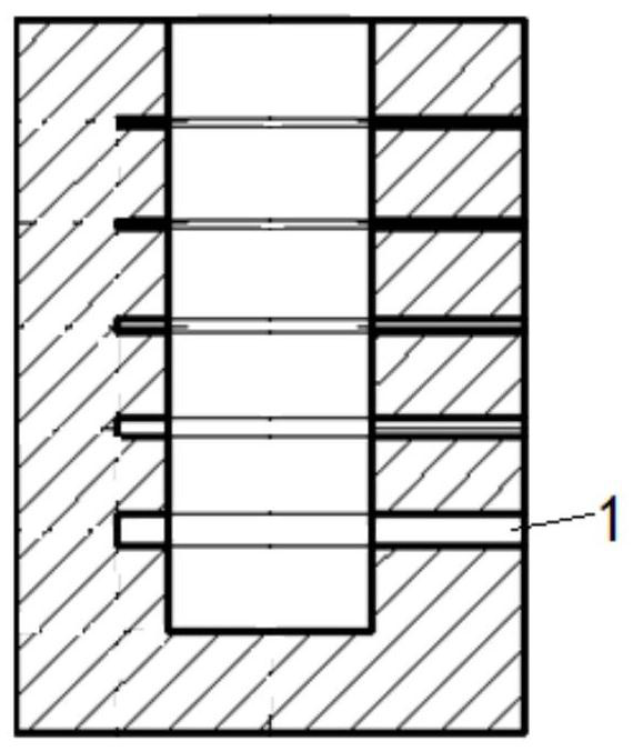
[0005] Since the joint surface of the steel substrate and the copper tube in the rotor plunger hole comparison test block is a cylindrical surface, the current drilling method can only drill out the artificial defects of the flat-bottomed holes, but cannot drill the artificial defects of the cylindrical surface, resulting in the rotor plunger hole. The simulation of the welding interface of the comparison test block and the actual welding interface at the rotor plunger hole is insufficient, and the thickness of the copper tube is very thin (0.6mm), so the drill bit can easily drill through the copper-steel interface and damage the copper tube, resulting in the collection of It is difficult to identify the ultrasonic reflected wave of the artificial defect and the original wave mixed together, and the evaluation of the defect equivalent size of the tested rotor will cause serious misjudgment or cannot be evaluated
Although the welded interface in the rotor end face comparison test block and the welded interface at the rotor end face can be fully simulated, there is still the problem that the drill bit is easy to drill through the copper-steel interface and damage the copper plate, resulting in the collection of artificial defects. Inaccurate, when the copper layer is very thin, the reflected wave of the artificial defect will be mixed with the initial wave, which is difficult to identify, and the evaluation of the equivalent size of the defect of the tested rotor will cause serious misjudgment or cannot be evaluated
[0006] Therefore, when the test block produced by the existing test block production method is used for ultrasonic inspection and quality evaluation of the rotor, there are defects that will cause serious misjudgment when evaluating the equivalent size of the defect.

Method used


Image

  • Manufacturing method of test block forultrasonic detection of non-welding defect of diffusion welding interface
  • Manufacturing method of test block forultrasonic detection of non-welding defect of diffusion welding interface
  • Manufacturing method of test block forultrasonic detection of non-welding defect of diffusion welding interface

Examples


Embodiment Construction

[0028] The present invention will be further described below in conjunction with the accompanying drawings and embodiments, but not as a basis for limiting the present invention.

[0029] Example. A method for making a test block for ultrasonic detection of unwelded defects in a diffusion welding interface, including a method for making a comparison test block for a rotor plunger hole and a method for making a comparison test block for a rotor end face;

[0030] The manufacturing method of the comparison test block of the rotor plunger hole comprises the following steps,

[0031] a. If figure 1 As shown, first drill a plurality of horizontal holes 1 with different diameters on the side of a steel substrate (there is a plunger hole in the axial direction), and the horizontal holes 1 penetrate to the plunger hole or pass through the plunger hole to obtain product A.

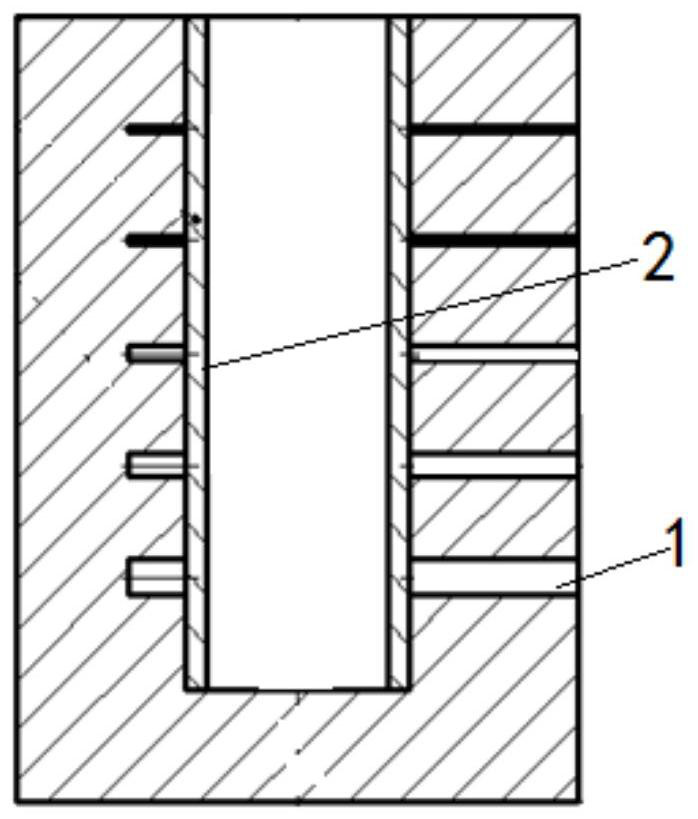
[0032] b. If figure 2 As shown, the product A and the copper tube 2 are connected as a whole by diffusion w...


PUM

PropertyMeasurementUnit
diameteraaaaaaaaaa

Abstract

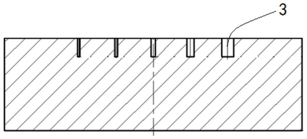
The invention discloses a manufacturing method of a test block for ultrasonic detection of a non-welding defect of a diffusion welding interface. The manufacturing method comprises a manufacturing method of a rotor plunger hole comparison test block and a manufacturing method of a rotor end face comparison test block. The manufacturing method of the rotor plunger hole reference block comprises the following steps: a, drilling a plurality of transverse holes with different diameters on the side surface of a steel substrate to obtain a product A, and b, connecting the product A and a copper pipe into a whole by utilizing diffusion welding to obtain a finished product of the rotor plunger hole reference block, the manufacturing method of the rotor end face comparison test block comprises the following steps: c, drilling a plurality of vertical holes with different diameters on the end face of another steel substrate to obtain a product C, and d, connecting the product C and a copper plate into a whole by utilizing diffusion welding to obtain a finished product of the rotor end face comparison test block. The test block manufactured by the method is used for ultrasonic detection and quality evaluation of the rotor, and has the advantage that serious misjudgment cannot be caused when the equivalent dimension of the defect is evaluated.

Description

technical field [0001] The invention belongs to the field of ultrasonic detection of unwelded defects in diffusion welding interfaces, and in particular relates to a method for making a test block for ultrasonic detection of unwelded defects in diffusion welding interfaces. Background technique [0002] Diffusion welding is a welding method that welds two metal parts with different properties together, such as the core component (rotor) of the hydraulic pump of the aerospace hydraulic system, including a cylindrical steel substrate with a column on the top surface of the steel substrate. The plug hole and the plunger hole are diffusion-welded with a copper tube with a thickness of about 0.6mm, and the bottom surface of the steel substrate is equipped with a copper plate with a thickness of about 0.6mm. Make the performance of the rotor better. [0003] With the rapid development of the aerospace industry, more stringent requirements are put forward for the reliability and p...

Claims


Application Information

Patent Timeline
Patent Type & Authority Applications(China)
IPC IPC(8): G01N1/28G01N29/04
CPCG01N1/28G01N29/04
Inventor 贺亚军龙飞侯昆文飞燕卓著胡洪林杨先
Owner AVIC LIYUAN HYDRAULIC
Learn More