A guided wave propagation characteristic solving method and system

A technology of wave propagation and characteristics, which is applied in the field of solving guided wave propagation characteristics, can solve problems such as heavy workload, inability to analyze guided wave propagation characteristics, and inability to analyze guided wave propagation characteristics in shear mode, achieving high solution efficiency, The analysis process is simple and easy to operate, and the effect of improving the solution accuracy

Pending Publication Date: 2021-06-11
NANJING UNIV OF TECH
View PDF4 Cites 0 Cited by
  • Summary
  • Abstract
  • Description
  • Claims
  • Application Information

AI Technical Summary

Problems solved by technology

[0004] The first method requires programming and different codes need to be written for different materials and different cross-sections, which requires a lot of work
The second method cannot analyze the guided wave propagation characteristics of the shear mode of an arbi

Method used


Image

  • A guided wave propagation characteristic solving method and system
  • A guided wave propagation characteristic solving method and system
  • A guided wave propagation characteristic solving method and system

Examples


Embodiment 1

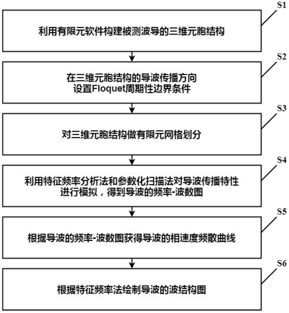
[0059] like image 3 Shown is a flow chart of a solution method for guided wave propagation characteristics in Embodiment 1 of the present invention. In Embodiment 1 of the present invention, a method for solving the propagation characteristics of guided waves is introduced, which includes the following steps:

[0060] Using finite element software to construct the three-dimensional cellular structure of the waveguide under test;

[0061] Set the Floquet periodic boundary condition in the direction of the guided wave propagation of the three-dimensional cellular structure;

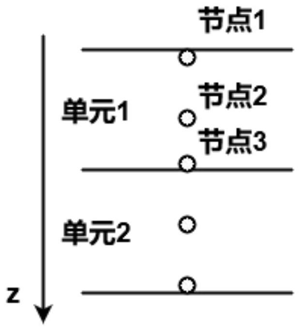
[0062] Perform finite element meshing on 3D cellular structures;

[0063] Using the characteristic frequency analysis method and the parametric scanning method to simulate the propagation characteristics of the guided wave, and obtain the frequency-wavenumber diagram of the guided wave;

[0064] Obtain the phase velocity dispersion curve of the guided wave according to the frequency-wavenumber diagram o...

Embodiment 2

[0077] Some steps in the embodiment 1 are described in more detail in the embodiment 2 of the present invention. Specifically, in Embodiment 2 of the present invention, a plate is taken as an example, and a guided wave propagation characteristic of a cell structure in the shape of a small cuboid is solved.

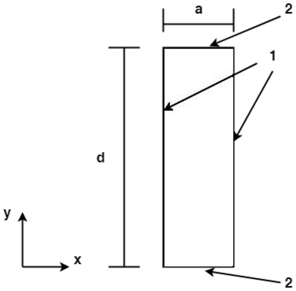
[0078] like Figure 4 Shown is a schematic structural view of the three-dimensional cellular structure in Example 2 of the present invention. Among them, xyz represents a three-dimensional coordinate system; where x is the direction of guided wave propagation, z is the thickness direction; a represents the distance from the source boundary to the target boundary; d represents the thickness of the cellular structure; 1 represents the Floquet periodic boundary condition; 2 represents the free Boundary conditions; 3 means continuity boundary conditions.

[0079] Three-dimensional modeling is carried out on the measured waveguide to obtain a three-dimensional cellular struct...

Embodiment 3

[0085] Embodiment 3 of the present invention introduces a system for solving the propagation characteristics of guided waves, which is implemented based on the method for solving the propagation characteristics of guided waves in Embodiment 1 of the present invention. The system includes cell building module, boundary condition setting module, grid division module, scanning simulation module, calculation module and drawing module.

[0086] Among them, the cellular construction module is used to construct the three-dimensional cellular structure of the measured waveguide by using finite element software;

[0087] The boundary condition setting module is used to set the Floquet periodic boundary condition in the direction of wave propagation of the three-dimensional cellular structure;

[0088] The meshing module is used for finite element meshing of the three-dimensional cellular structure;

[0089] The scanning simulation module is used to scan the three-dimensional cellular ...


PUM


Abstract

The invention relates to a guided wave propagation characteristic solving method and system, and belongs to the field of nondestructive testing. The method specifically comprises the following steps: constructing a three-dimensional cellular structure of a waveguide to be tested by utilizing finite element software; setting floquet periodic boundary conditions in the guided wave propagation direction of the three-dimensional cellular structure; performing finite element grid division on the three-dimensional cellular structure; utilizing a characteristic frequency analysis method and a parameterized scanning method to simulate guided wave propagation characteristics, and importing output data of finite element software into MATLAB for data processing to obtain a frequency-wave number diagram of guided waves; obtaining a frequency dispersion curve of the guided wave according to the frequency-wave number diagram of the guided wave; and drawing a wave structure chart of the guided wave according to a characteristic frequency analysis method. According to the method and the system, the solving process of the guided wave propagation characteristics can be simplified, and the method and the system are suitable for solving the pilot frequency propagation characteristics of any waveguide structure made of different materials.

Description

technical field [0001] The invention relates to the field of non-destructive testing, in particular to a method and system for solving the propagation characteristics of guided waves. Background technique [0002] Common waveguide structures include metal plates, metal pipes, composite plates, composite pipes, etc. These structures will inevitably have various defects or damages during production and use, and these defects or damages will affect their service life. cause safety accidents. In order to ensure safe use, it is necessary to carry out non-destructive testing and evaluation on the above-mentioned waveguide structure. [0003] Generally, the waveguide structure is scanned by ultrasonic guided waves, and whether the waveguide structure has defects or damages is judged based on the propagation characteristics of the guided waves. There are currently two methods: SAFE method (semi-analytical finite element method) and a method combining two-dimensional models with Fl...

Claims


Application Information

Patent Timeline
IPC IPC(8): G06F30/23
CPCG06F30/23
Inventor 石颖颖赵金玲赵建平李念
Owner NANJING UNIV OF TECH
Why Eureka
Try Eureka