
Method for producing cylindrical sputtering target

A manufacturing method and cylindrical technology, applied in the directions of sputtering plating, vacuum evaporation plating, coating, etc., can solve the problems of poor bonding, time-consuming, difficult to avoid poor bonding, etc., to prevent poor bonding and improve the finished product. Good efficiency and workability

Inactive Publication Date: 2021-06-15
MITSUBISHI MATERIALS CORP
View PDF10 Cites 0 Cited by
  • Summary
  • Abstract
  • Description
  • Claims
  • Application Information

AI Technical Summary

Problems solved by technology

[0014] However, in the case of Patent Document 2, the work for stirring the joining material takes time
In addition, in order to remove the oxide film of the applied bonding material on the entire surface, it is necessary to stir the entire gap between the target and the liner, and there is a high possibility of poor bonding in the part where the stirring is insufficient.
[0015] Also in Patent Document 3, it is necessary to separately install a vibration source for vibrating the powder material as another device, and if the stirring of the solder by the vibration of the powder material is insufficient, bonding failure may sometimes be caused.
[0016] In the manufacturing method of Patent Document 4, if an oxide film adheres to the outer peripheral surface of the solid bonding material or the inner and outer peripheral surfaces of the target and the liner before bonding, it is difficult to avoid bonding defects.

Method used

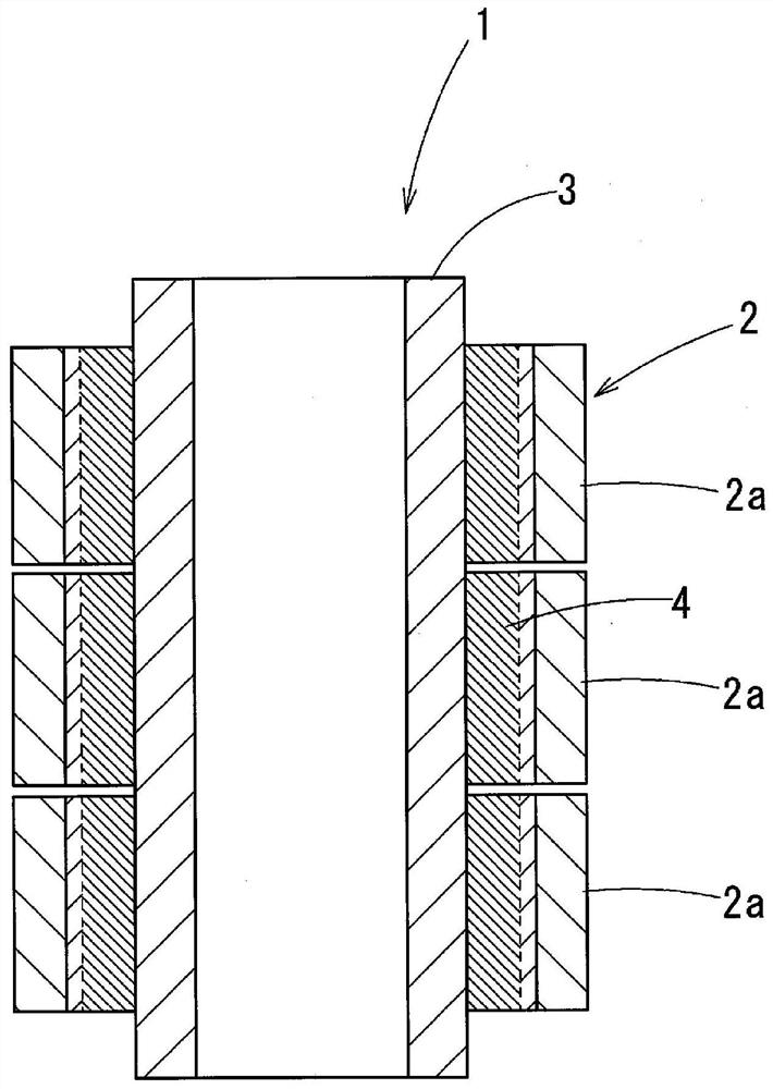
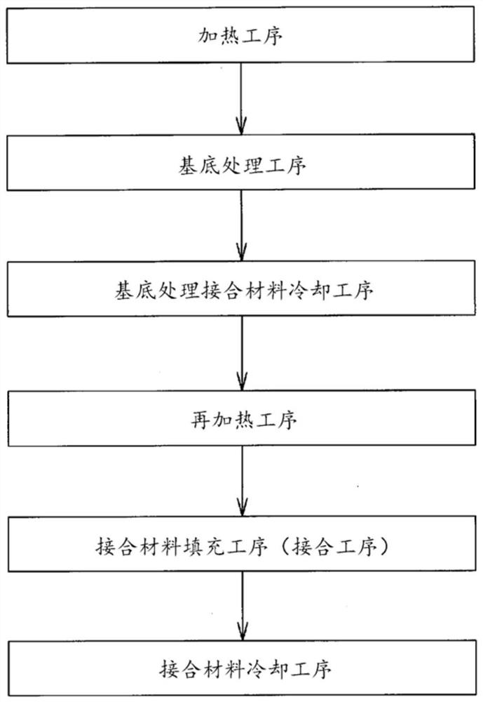
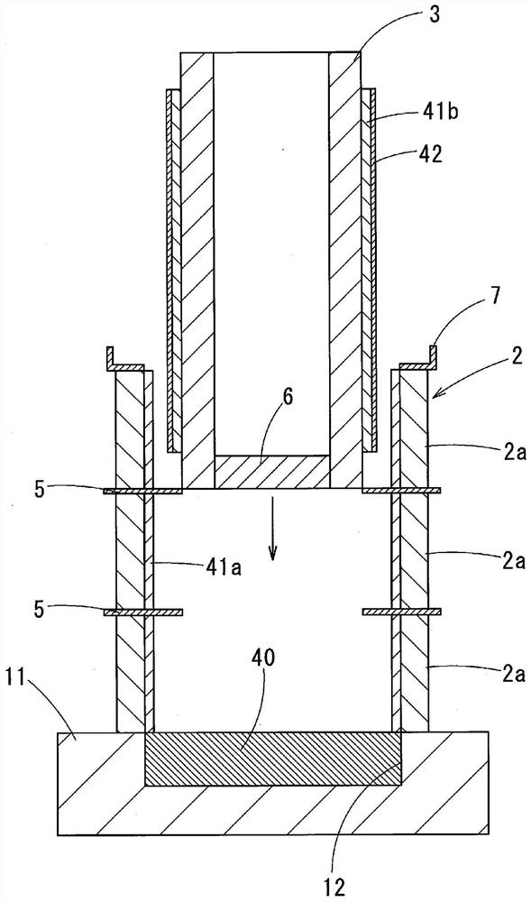

Image

  • Method for producing cylindrical sputtering target
  • Method for producing cylindrical sputtering target
  • Method for producing cylindrical sputtering target

Examples


Embodiment

[0086] In order to confirm the effects of the present invention, experiments were conducted. For the target and the liner, materials of the material type shown in Table 1 were used, and a material coated with a surface-treated bonding material and a material not coated with a surface-treated bonding material were prepared. In addition, SIZ, which is the target type in Example 4, means a sintered oxide of Si, In, and Zr, AZO in Example 5 means a sintered oxide of Al and Zn, and CuNi in Example 6 means a sintered oxide of Cu and Ni. As for the alloy, CuCuO in Example 7 refers to a sintered body of Cu and CuO, and CuGa in Examples 8 to 11 and Comparative Example 2 refers to an alloy of Cu and Ga. As described in Table 1, pure indium, tin alloy, and pure tin were used as the substrate treatment bonding material. When performing surface treatment, use warm air to heat until the surface temperature reaches 240°C to 260°C, apply the surface treatment bonding material in the atmosphe...


PUM


Abstract

The method of the present invention has: an undercoating step for forming an undercoating layer by coating an undercoating bonding material on the inner surface of a target material and / or the outer surface of a backing tube; and a bonding step for inserting the backing tube inside the target material after the undercoating step and filling a filler bonding material in the gap between the target material and the backing tube. In the bonding step: a scraping plate that can be disposed so as to protrude radially in the gap is provided along the circumferential direction on one or both of the target material and the backing tube; and, with the undercoating layer heated so the surface thereof is in at least a half-melted state, the backing tube is inserted inside the target material while scraping the oxide film formed on the surface of the undercoating layer with the scraping plate.

Description

technical field [0001] The present invention relates to a method of manufacturing a cylindrical sputtering target used in a sputtering device. [0002] This application claims priority based on Japanese Patent Application No. 2018-242356 filed in Japan on December 26, 2018, and uses the content thereof here. Background technique [0003] There is known a sputtering device that performs sputtering while rotating a cylindrical sputtering target. As disclosed in Patent Document 1, in a cylindrical sputtering target used in such a sputtering device, the inner peripheral surface of the cylindrical target is bonded to the outer peripheral surface of the cylindrical liner. [0004] In this bonding, a bonding method is known in which a substrate-treated bonding material that is the same as or similar to the bonding material is applied to the outer peripheral surface of a cylindrical liner and the inner peripheral surface of a cylindrical target to be bonded. The substrate is treat...

Claims


Application Information

Patent Timeline
Patent Type & Authority Applications(China)
IPC IPC(8): C23C14/34
CPCC23C14/34C23C14/3407H01J37/3491H01J37/3423H01J37/3435
Inventor 冈野晋大友健志
Owner MITSUBISHI MATERIALS CORP
Learn More