Flat plate electrospray emission device with micro channels

A launch device, electrospray technology, applied in the direction of electrostatic spray device, spray device, spray electric energy device, etc., can solve the problems that cannot be disassembled and repaired, the silicon-based material is easily damaged, and it is not easy to expand on a large scale, so as to achieve improvement and scalability performance, stable operation, and avoidance of diffusion and coalescence problems

Active Publication Date: 2021-06-18
CHONGQING UNIV
View PDF20 Cites 1 Cited by
  • Summary
  • Abstract
  • Description
  • Claims
  • Application Information

AI Technical Summary

Problems solved by technology

[0003] At present, most of the existing electrospray emitters are in the form of capillary tubes. The processing accuracy of this method is limited, and it is not easy to expand on a large scale, which seriously limits the application of this technology in the fields of chip heat dissipation and microfluidics. The electrospray emitter produced by processing technology has good expandability, but the silicon-based material after etching is easily damaged and the service life is low; the use of flat microholes as the emitter can avoid the above problems, but when spraying working fluids with low surface tension When the Taylor cone will inevitably expand and coalesce, resulting in spray failure or even surface breakdown, causing safety problems; and most of the above-mentioned launcher designs are bonded by glue, which cannot be disassembled and repaired

Method used


Image

  • Flat plate electrospray emission device with micro channels
  • Flat plate electrospray emission device with micro channels
  • Flat plate electrospray emission device with micro channels

Examples


Embodiment Construction

[0018] The technical solutions of the present invention will be further described in detail below in conjunction with the accompanying drawings and specific implementation examples. However, it should be noted that implementation of the present invention is not limited to the following embodiments.

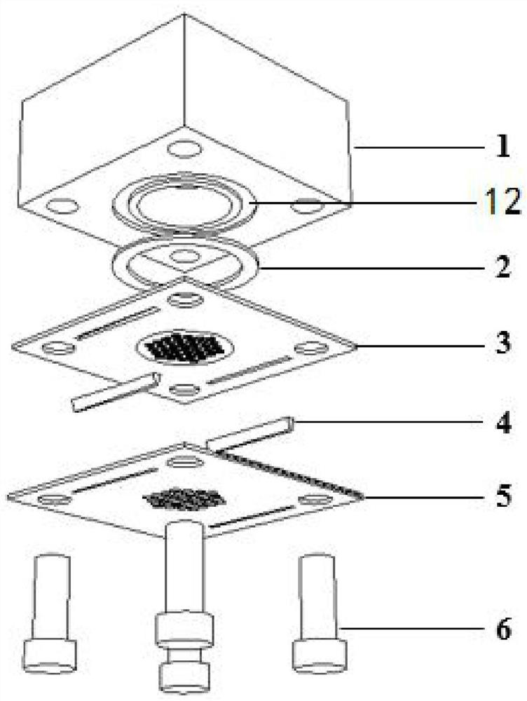
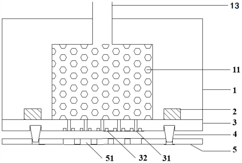
[0019] see Figure 1 to Figure 3 , a flat electrospray emission device with micro channels, comprising a liquid storage tank 1, a flat plate emitter 3 and an extraction electrode 5 arranged sequentially from top to bottom; the liquid storage tank 1 is provided with a porous dielectric material 11 and the working substance required for electrospray; a liquid outlet hole 12 is provided at the center of the lower end plate of the liquid storage tank 1, and an inlet connecting pipe 13 is arranged on the liquid storage tank 1, and the flat emitter 3 and the outlet The corresponding position of the liquid hole is provided with some emission holes 31, and the extraction electrode 5 is p...


PUM


Abstract

The invention discloses a flat plate electrospray emission device with micro channels. The flat plate electrospray emission device comprises a liquid storage tank, a flat plate emitting electrode and an extraction electrode which are sequentially arranged from top to bottom. The flat plate electrospray emission device is characterized in that a porous medium material and working media needed by electrospray are arranged in the liquid storage tank; a liquid outlet hole is formed in the center of a lower end plate of the liquid storage tank, a plurality of emitting holes are formed in the portion, corresponding to the liquid outlet hole, of the flat plate emitting electrode, a plurality of micro holes are formed in the extraction electrode, and the emitting holes correspond to the micro holes one to one; the annular channels are formed in the peripheries of the emitting holes of the flat plate emitting electrode respectively and located on the lower end face of the flat plate emitting electrode; a positioning column is arranged between the flat plate emitting electrode and the extraction electrode; the flat plate emitting electrode is used for distributing the spray flow and controlling the Taylor cone form formed by the electrospray working media near the emitting holes; and the extraction electrode is used for improving the electric field intensity near the emitting holes and controlling the spray plume and the deposition form of the micro holes. The flat plate electrospray emission device can be widely applied to the fields of agriculture, sanitation, mass spectrometry, space propulsion and the like.

Description

technical field [0001] The invention relates to the field of spray emission devices, in particular to a flat electrospray emission device with micro-grooves. Background technique [0002] Electrospray technology is widely used in pesticide spraying, environmental disinfection, mass spectrometry, space propulsion and other fields. The emitter is a key component that determines the performance of electrospray, and its manufacturing materials and integration process have an important impact on the stability and economy of electrospray. [0003] At present, most of the existing electrospray emitters are in the form of capillary tubes. The processing accuracy of this method is limited, and it is not easy to expand on a large scale, which seriously limits the application of this technology in the fields of chip heat dissipation and microfluidics. The electrospray emitter produced by processing technology has good expandability, but the silicon-based material after etching is easi...

Claims


Application Information

Patent Timeline
Patent Type & Authority Applications(China)
IPC IPC(8): B05B5/053
CPCB05B5/053B05B5/0533
Inventor 王宏于涵朱恂陈蓉丁玉栋程旻吴君军廖强
Owner CHONGQING UNIV
Why Eureka
Try Eureka