

Laser welding tool
A laser welding and tooling technology, applied in laser welding equipment, welding equipment, welding equipment and other directions, can solve the problems of unstable lap gap control, difficult welding, etc., to achieve compact structure, reasonable mechanism layout, and meet the welding process and quality. the effect of the request
- Summary
- Abstract
- Description
- Claims
- Application Information
AI Technical Summary
Problems solved by technology
Method used
Image

Examples
Embodiment 1
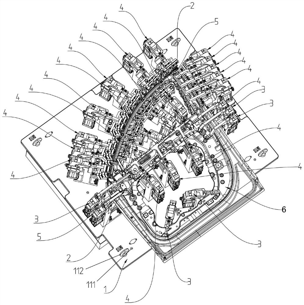
[0038] This embodiment provides a laser welding tool, such as figure 1 As shown, it includes: tooling base plate 1, positioning pin assembly 2, positioning clamping assembly 3 and welding seam positioning clamping assembly 4; and the positioning pin assembly 2, positioning clamping assembly 3 and welding seam positioning clamping assembly 4 All are connected with the tooling base plate 1;
[0039] Wherein, the positioning pin assembly 2 is used to cooperate with the positioning hole 5 on the workpiece 6, and the positioning clamping assembly 3 is used to clamp the surface of the workpiece 6, and the positioning of the workpiece is completed by the positioning pin assembly 2 and the positioning clamping assembly 3. 6; and the welding seam positioning clamp assembly 4 is used to fix the welding seam of the workpiece 6.
[0040] In this embodiment, there can be multiple positioning pin components 2, positioning clamping components 3 and weld positioning clamping components 4, wh...
Embodiment 2
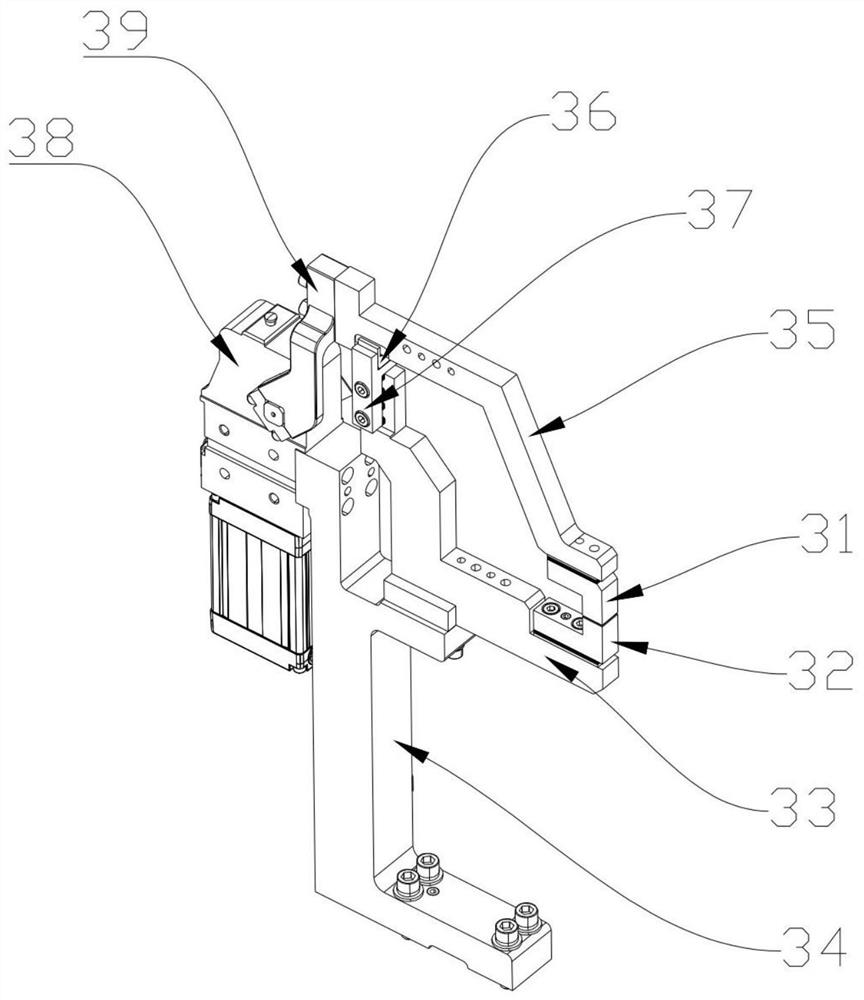
[0051] The only difference between this embodiment and Embodiment 1 is that, as Figure 3a-3b As shown, the positioning clamp assembly 3 also includes:
[0052] The first clamping positioning block 31 is connected to the lower surface of the other end of the workpiece clamping arm 35;
[0053] The second clamping positioning block 32, which is connected to the upper surface of the workpiece positioning adapter plate 33, and corresponds to the position of the first clamping positioning block 31, the first clamping positioning block 31 and the second clamping positioning block 31 A clamping space for clamping the workpiece 6 is formed between the positioning blocks 32; when the power output shaft of the clamping cylinder 38 drives the rotating arm 39 to rotate, the first clamping positioning block 31, the second clamping The tight positioning block 32 is in contact with the surface of the workpiece 6 to achieve clamping of the workpiece 6; meanwhile, the connection between the ...
Embodiment 3
[0060] The only difference between this embodiment and embodiment 1 or 2 is that, as Figures 5a-5b As shown, in the welding seam positioning and clamping assembly 4, the upper welding seam clamping block 41 is provided with an accommodating cavity 411 for accommodating the welding seam and penetrating up and down, and the upper part of the accommodating cavity 411 has an opening 4111 The aperture is larger than the aperture of the lower opening 4112, and the whole is a trumpet-shaped structure whose outer peripheral surface is inclined relative to the horizontal plane. Preferably, the angle α formed between the outer peripheral surface of the accommodating cavity 411 and the horizontal plane satisfies the condition: 60°≤α≤85° (preferably α is 75°), thus, even if there is a certain deflection angle when the laser is applied to the weld seam, since the upper opening 4111 of the housing cavity 411 has a relatively large aperture and the upper space is relatively open, the laser w...
PUM
| Property | Measurement | Unit |
|---|---|---|
| Weld length | aaaaa | aaaaa |
| Weld width | aaaaa | aaaaa |
Abstract
Description
Claims
Application Information