Textile processing equipment capable of reducing dye liquor impurities and improving quality of printed and dyed cloth

A technology of processing equipment and impurities, applied in the field of textile processing equipment, can solve the problems of difficulty in meeting the needs of fast-paced textile printing and dyeing processing, easily affecting the quality of textile printing and dyeing processing, and impurity cannot be removed in time, so as to improve the filtering effect and avoid mesh clogging. , the effect of increasing the speed

Active Publication Date: 2021-06-18
杭州华伟兴业印染有限公司
View PDF7 Cites 0 Cited by
  • Summary
  • Abstract
  • Description
  • Claims
  • Application Information

AI Technical Summary

Problems solved by technology

[0005] In order to solve the above-mentioned technical problems, the present invention provides a textile processing equipment that reduces dye liquor impurities and improves the quality of printed and dyed cloth, so as to solve the existing similar reduction of dye liquor impurities and improve When using textile processing equipment with the quality of printed and dyed cloth, it is difficult to intercept and filter the impurities contained in the textile printing and dyeing slurry during the mixing process of the textile printing and dyeing slurry. After the printing and dyeing slurry is filtered, the impurities cannot be discharged in time, and it takes a long time to meet the needs of fast-paced textile printing and dyeing processing.

Method used


Image

  • Textile processing equipment capable of reducing dye liquor impurities and improving quality of printed and dyed cloth
  • Textile processing equipment capable of reducing dye liquor impurities and improving quality of printed and dyed cloth
  • Textile processing equipment capable of reducing dye liquor impurities and improving quality of printed and dyed cloth

Examples


Embodiment

[0028] as attached figure 1 to attach Figure 6 Shown:

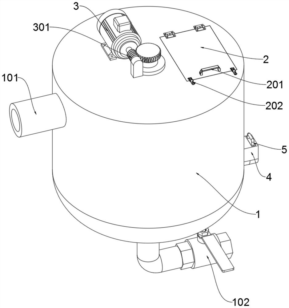
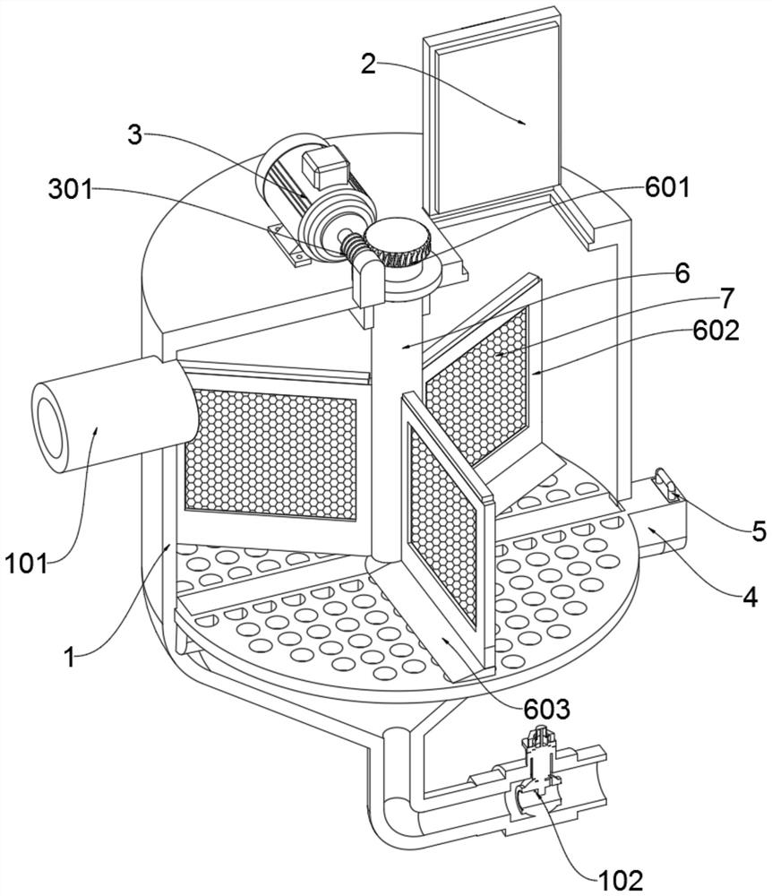
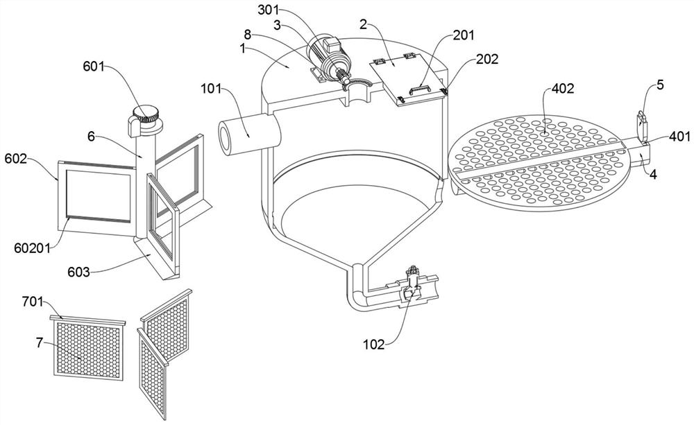
[0029] The present invention provides a textile processing equipment for reducing dye liquor impurities and improving the quality of printed and dyed cloth, which includes a filter barrel 1; a slag discharge tank 4 is arranged through the left and right sides of the filter barrel 1, and the right end of the slag discharge tank 4 is slidably connected with a slag tank stopper Plate 5; the top right side hinge of filter bucket 1 is connected with inspection door 2, and the length of inspection door 2 is identical with the length of filter screen 7, and the front end of inspection door 2 top is provided with door handle 201, and the left and right sides of door handle 201 are provided with There is a convenient lock 202. When in use, open the convenient lock 202, then pull the door handle 201 and pull it backwards, the inspection door 2 can be opened, and the filter screen in the filter barrel 1 can be checked through the ...


PUM


Abstract

The invention provides textile processing equipment capable of reducing dye liquor impurities and improving the quality of printed and dyed cloth. The equipment comprises a filtering barrel; a residue discharging groove is formed in the filtering barrel in a left-right penetrating mode; the right end of the residue discharging groove is slidably connected with a residue groove baffle; an inspection door is hinged to the right side of the top of the filtering barrel; a driving motor is mounted on the rear side of the top of the filtering barrel and is in transmission connection with a rotating roller which is rotationally connected to the middle of the top of the filtering barrel; and a resistance reducing ball is arranged at the rotating joint of the rotating roller and the top of the filtering barrel. According to the invention, a filtering screen is inserted into a slot of a filtering frame, so that the filtering screen can be fixed in the filtering frame; and when the rotating roller rotates in the filtering barrel, the filtering screen in the filtering frame can intercept and filter impurities in printing and dyeing size, and the impurities are attached to the filtering screen, so that the impurities are prevented from continuously floating in the printing and dyeing size, and the filtering effect on the impurities in the printing and dyeing size is improved.

Description

technical field [0001] The invention belongs to the field of textile technology, and more specifically relates to a textile processing equipment for reducing impurities in dye liquor and improving the quality of printed and dyed cloth. Background technique [0002] Textile printing and dyeing slurry is a general term for the viscous natural and synthetic polymers used in the textile field. In the textile process, it is necessary to use textile printing and dyeing slurry to assist weaving. Most of the existing textile printing and dyeing slurry , it needs to be stirred before use to make it evenly mixed. [0003] For textile processing equipment that reduces dye liquor impurities and improves the quality of printed and dyed cloth, refer to Patent No. CN211311111U, which mainly includes a casing and a matching airtight door. The upper end of the body is provided with a feeding mechanism, and the output end of the feeding mechanism penetrates the side wall of the housing and e...

Claims


Application Information

Patent Timeline
IPC IPC(8): D06B23/14D06B23/20
CPCD06B23/14D06B23/20
Inventor 岳永祥
Owner 杭州华伟兴业印染有限公司
Why Eureka
Try Eureka