
Gas turbine pneumatic control system based on three-dimensional axial flow

A pneumatic control system and gas turbine technology, applied in the direction of fuel control of turbine/propulsion device, turbine/propulsion fuel delivery system, charging system, etc., can solve the problem of including the thickness of carbon deposit in the uncombusted chamber into the control parameters, and the lack of automatic adjustment of gas turbine fuel Input volume and other issues to achieve the effect of improving work efficiency and reliability, avoiding panting, and improving combustion efficiency

Active Publication Date: 2021-06-18
山东赛马力发电设备有限公司
View PDF7 Cites 0 Cited by
  • Summary
  • Abstract
  • Description
  • Claims
  • Application Information

AI Technical Summary

Problems solved by technology

[0003] 1. Traditional gas turbines do not automatically adjust the fuel input, fuel temperature, and intake air volume of the gas turbine in real time according to the operating status of the gas turbine
[0004] 2. In traditional gas turbines, the thickness of carbon deposits in the combustion chamber is not included in the control parameters

Method used


Image

  • Gas turbine pneumatic control system based on three-dimensional axial flow
  • Gas turbine pneumatic control system based on three-dimensional axial flow
  • Gas turbine pneumatic control system based on three-dimensional axial flow

Examples


Embodiment Construction

[0050] The above and other technical features and advantages of the present invention will be described in more detail below in conjunction with the accompanying drawings.

[0051] Preferred embodiments of the present invention are described below with reference to the accompanying drawings. Those skilled in the art should understand that these embodiments are only used to explain the technical principles of the present invention, and are not intended to limit the protection scope of the present invention.

[0052] It should be noted that, in the description of the present invention, terms such as "upper", "lower", "left", "right", "inner", "outer" and other indicated directions or positional relationships are based on the terms shown in the accompanying drawings. The direction or positional relationship shown is only for convenience of description, and does not indicate or imply that the device or element must have a specific orientation, be constructed and operated in a spec...


PUM


Abstract

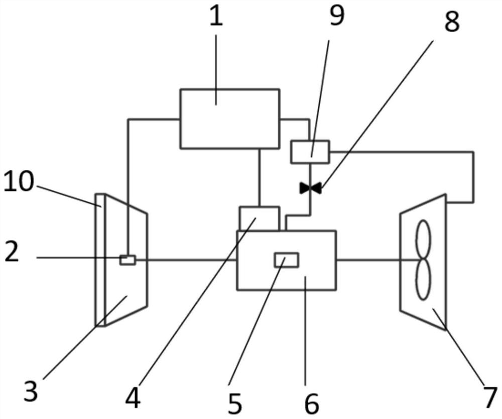
The invention relates to a gas turbine pneumatic control system based on three-dimensional axial flow. A central control processor is arranged to be connected with an ultrasonic detector, a temperature detector, a rotating speed detector and flow detection equipment and complete data exchange in real time; and meanwhile, the central control processor adjusts the opening and closing degree of an adjusting valve and an guide vane opening and closing angle in real time according to the carbon deposition thickness detected by the ultrasonic detector and the change of the axial flow in a gas compressor, so that the combustion effect in a combustion chamber of a gas turbine is improved; and meanwhile, high-temperature deformation of a gas turbine impeller caused by too high rotation speed of the gas turbine impeller or low efficiency caused by too slow rotation of the gas turbine impeller are avoided, so that the gas turbine is in a stable operation state, and the working efficiency and reliability of the gas turbine are improved.

Description

technical field [0001] The field of the invention is specifically a gas turbine aerodynamic control system based on three-dimensional axial flow. Background technique [0002] In the main process of air and gas in the gas turbine, only the gas turbine cycle composed of three major components: the compressor (Compressor), the combustor (Combustor) and the gas turbine (Turbine), is generally called a simple cycle, and the compressor sucks in air from the external atmosphere , and is compressed step by step by the axial flow compressor to increase the pressure, and the air temperature is also increased accordingly; the compressed air is sent to the combustion chamber and mixed with the injected fuel to generate high-temperature and high-pressure gas; and then enters the turbine Expansion works, pushing the turbine to drive the compressor and the external load rotor to rotate together at high speed, realizing the partial conversion of the chemical energy of the gas or liquid fue...

Claims


Application Information

Patent Timeline
Patent Type & Authority Applications(China)
IPC IPC(8): F02C9/54
CPCF02C9/54
Inventor 殷爱军曹政坤陈光亮丁磊张扬军钱煜平侯跃艳
Owner 山东赛马力发电设备有限公司
Learn More