
Efficient submerged combustion type gasifier

A submerged combustion and gasifier technology, applied in pressure vessels, heat storage heaters, non-pressure vessels, etc., can solve the problems of poor sealing of cover plates, low heat exchange efficiency, and poor anti-corrosion effect, and achieve Prevent corrosion of panels, improve heat exchange efficiency, and prevent damage

Active Publication Date: 2021-06-18
江苏中圣压力容器装备制造有限公司
View PDF8 Cites 0 Cited by
  • Summary
  • Abstract
  • Description
  • Claims
  • Application Information

AI Technical Summary

Problems solved by technology

[0005] The purpose of the present invention is to provide a high-efficiency heat exchange tube bundle for the shortcomings of the existing submerged combustion gasifier, such as the low heat exchange efficiency and the poor sealing performance of the cover plate used, easy leakage, and poor anti-corrosion effect. , The high-efficiency submerged combustion gasifier of the new water bath cover plate significantly improves the heat exchange efficiency, and the new water bath cover plate has good sealing performance and good drainage performance

Method used


Image

  • Efficient submerged combustion type gasifier
  • Efficient submerged combustion type gasifier
  • Efficient submerged combustion type gasifier

Examples


Embodiment 1

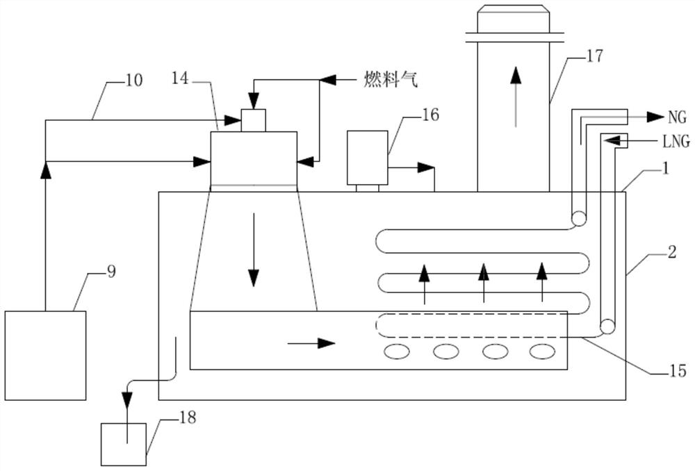
[0042] Such as figure 1 As shown, a high-efficiency submerged combustion gasifier includes a blower 9, an air duct 10, a burner 14, a water bath 2, a heat exchange tube bundle 15, an lye tank 16, a chimney 17, an overflow pool 18, and a water bath A sealing cover plate; the heat exchange tube bundle 15 is a high-efficiency heat exchange tube bundle composed of smooth tubes, and the material of the heat exchange tubes is stainless steel.

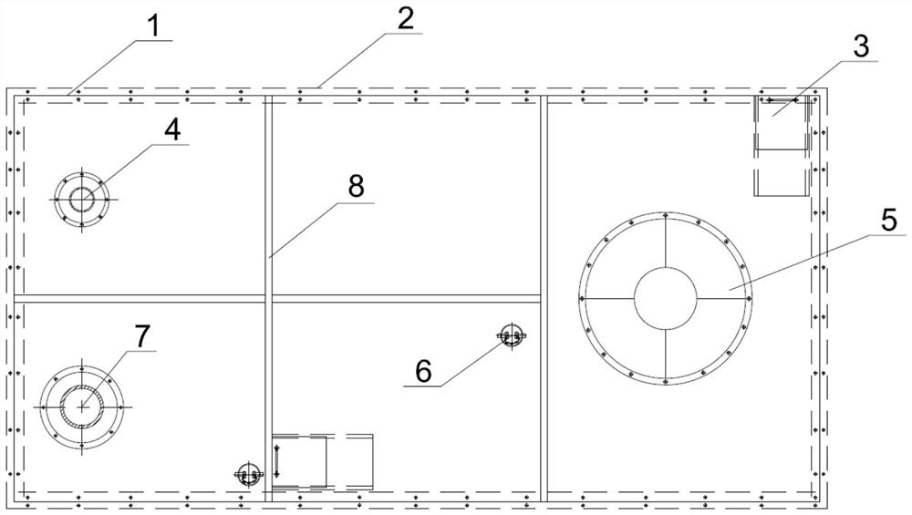
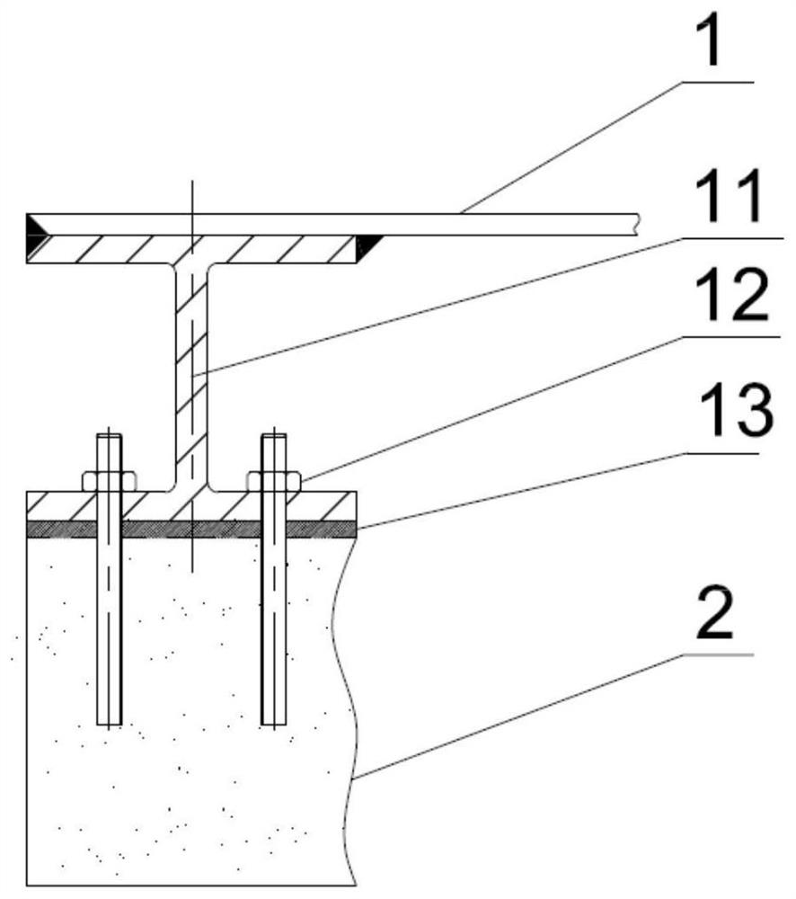
[0043] Such as Figure 2-Figure 9 As shown, the sealing cover plate for the water bath includes a panel 1, and the panel 1 is formed by splicing five patterned steel plates, leaving a gap with a width of 5-20 mm at the joint of two adjacent patterned steel plates. The lower surfaces of two adjacent checkered steel plates are provided with base plates 81 to form drains 8, and rubber gaskets are arranged between the lower surfaces of checkered steel plates and base plates 81. The base plates 82 are fixed to the checkered steel plates by bolts,...

Embodiment 2

[0053] On the basis of Embodiment 1, adjustment: the lower part of the edge of the observation hole 6 stretches out so that the edge of the observation hole 6 is stepped, and the upper part of the edge of the observation hole cover plate 61 stretches out so that the observation hole cover plate is stepped. The hole cover plate 61 is overlapped with the panel 1 .

Embodiment 3

[0055] The heat exchange tube bundle is a high-efficiency heat exchange tube bundle composed of corrugated tubes, and the material of the heat exchange tubes is stainless steel.


PUM


Abstract

The invention discloses an efficient submerged combustion type gasifier which comprises an air blower, an air duct, a combustor, a water bath pool, a heat exchange tube bundle, an alkali liquor tank, a chimney and a water bath pool sealing cover plate, wherein the water bath pool sealing cover plate comprises a panel, and the panel is formed by splicing a plurality of checkered steel plates; connecting steel pieces are arranged below the peripheral edge of the panel; the cover plate is fixed on the upper edge of the wall of the water bath pool through the connecting steel pieces; a drainage ditch is arranged at the joint of every two adjacent checkered steel plates; the panel is provided with a manhole, an LNG inlet tube hole for a heat exchange tube bundle LNG inlet tube in the water bath to pass through the cover plate, an NG outlet tube hole for a heat exchange tube bundle NG outlet tube to pass through the cover plate, a burner hole for installing a burner and an observation hole for observing the water bath. The heat exchange tube bundle can effectively improve the heat exchange efficiency; the cover plate can play a good sealing role, water in the water bath pool is prevented from being splashed out of the cover plate, and external water and impurities are also prevented from entering the water bath pool, so that equipment can run stably.

Description

technical field [0001] The invention belongs to the technical field of liquefied natural gas gasification, and relates to a novel submerged combustion gasifier, in particular to a high-efficiency heat exchange type submerged combustion gasifier which is easy to install and disassemble. [0002] technical background [0003] The submerged combustion gasifier (SCV) directly mixes the hot gas from fuel combustion with water for heat exchange. The heat exchange coil for heating LNG is immersed in a water bath, and the hot water heats and vaporizes the LNG in the heat exchange coil. SCV has a fast start-up speed and is suitable for quick start-up requirements in emergencies or peak shaving. [0004] The submerged combustion gasifier used in the existing LNG receiving station includes blower, air duct, burner, water bath, heat exchange tube bundle, lye tank, chimney, overflow pool, etc. After the air and fuel gas are fully mixed in the burner, the high-temperature flue gas produc...

Claims


Application Information

Patent Timeline
Patent Type & Authority Applications(China)
IPC IPC(8): F17C7/04F17C9/02F24H7/02
CPCF17C7/04F17C9/02F24H7/0266F17C2221/033F17C2223/0161F17C2227/0309
Inventor 郭宏新高辉刘丰刘世平
Owner 江苏中圣压力容器装备制造有限公司
Learn More