Time-of-flight method and structured light method fused structured light three-dimensional imaging system and method

A time-of-flight and three-dimensional imaging technology, applied in the field of three-dimensional measurement, can solve problems such as limited use scenarios, low accuracy in medium and long distances, and reduced system integration, so as to improve the speed of structured light three-dimensional imaging, reduce the number of frames, improve accuracy and work range effect

Active Publication Date: 2021-06-18
革点科技(深圳)有限公司
View PDF6 Cites 3 Cited by
  • Summary
  • Abstract
  • Description
  • Claims
  • Application Information

AI Technical Summary

Problems solved by technology

The advantage of the structured light method is that its lateral resolution and depth in the direction of the depth direction are much higher than that of the time-of-flight method at short distances. The disadvantage is that the accuracy in the middle and long distances is greatly reduced.
[0003] Generally, the structured light method has obvious advantages in short-distance three-dimensional imaging, and the time-of-flight method is more suitable for medium and long distances. How to combine the two methods to improve the applicability of the system is an important technical improvement method. Traditional methods use multiple methods. Sensor data fusion, this method of using discrete subsystems has many disadvantages, which reduces the integration of the system, and at the same time increases the cost and complexity, which greatly limits the use scenarios of this method

Method used


Image

  • Time-of-flight method and structured light method fused structured light three-dimensional imaging system and method
  • Time-of-flight method and structured light method fused structured light three-dimensional imaging system and method
  • Time-of-flight method and structured light method fused structured light three-dimensional imaging system and method

Examples


Embodiment Construction

[0030] The invention aims to use MEMS two-dimensional scanning technology to simultaneously realize structured light three-dimensional imaging and time-of-flight imaging in the same system, and perform data fusion to improve the accuracy and working range of the system. In order to achieve this purpose, this method provides the following example technical solutions:

[0031] (1) Building a hybrid imaging system based on MEMS time-of-flight and structured light

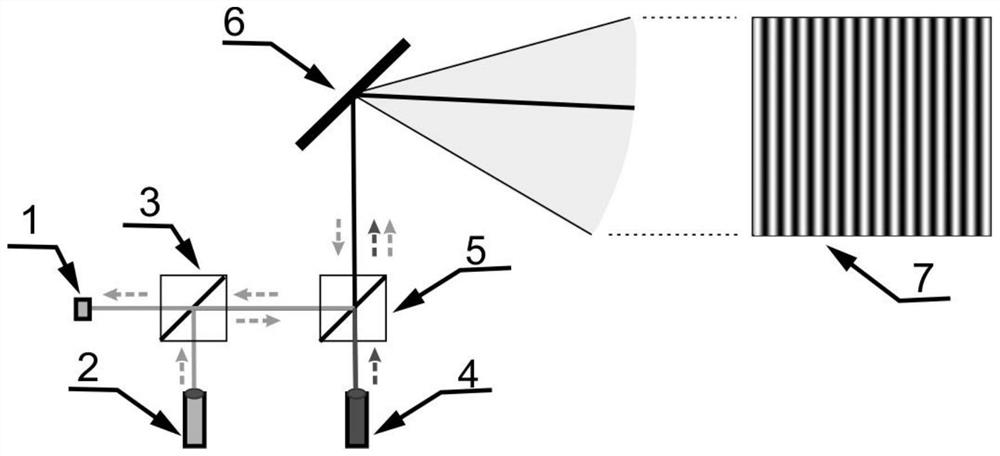
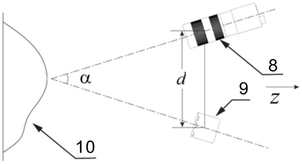
[0032] MEMS-based time-of-flight and structured light hybrid imaging systems, such as figure 2 As shown, the optical projector 9 is used to project the structured light light field, and emit and receive laser information for time-of-flight imaging; the image sensor 8 is used to capture the structured light information after the structured light is reflected by the measured object 10; the optical projection device such as figure 1 As shown, it is composed of a photodetector 1 , a first laser 2 , a first transflective...


PUM


Abstract

The invention discloses a time-of-flight method and structured light method fused structured light three-dimensional imaging system and method. The method comprises the following steps: constructing an MEMS-based time-of-flight method and structured light mixed imaging system; calibrating a coordinate transformation relation between a projection system and a camera; collecting data of a time-of-flight method and a structured light method; reconstructing low-precision three-dimensional data by using the time-of-flight method; reconstructing close-range high-precision three-dimensional data by using the low-precision three-dimensional data and the structured light method; and fusing the low-precision three-dimensional data and the high-precision three-dimensional data. An MEMS micromirror is used in cooperation with a laser and a digital camera, flight time three-dimensional imaging and structured light three-dimensional imaging are completed in the same system at the same time, data fusion is carried out, and the advantages of different imaging methods are brought into full play. Besides, the time-of-flight method is used to help the structured light method to perform phase unwrapping, the frame number of traditional structured light is reduced, and the structured light three-dimensional imaging speed in the method is greatly improved.

Description

Technical field: [0001] The invention relates to a structured light three-dimensional imaging system and method combining time-of-flight method and structured light method. It mainly uses MEMS micromirrors to cooperate with lasers and digital cameras to simultaneously complete time-of-flight three-dimensional imaging and structured light three-dimensional imaging in the same system. And carry out data fusion to give full play to the advantages of different imaging methods. The invention belongs to the field of three-dimensional measurement. Background technique: [0002] Time-of-flight (TOF) and structured light 3D imaging are the two most widely used 3D imaging technologies. The time-of-flight method uses a laser to irradiate the measured object, and then uses a photodetector to directly or indirectly measure the time difference from emission to reflection and then received by the photodetector to calculate the depth of the measurement point. Commonly used time-of-flight ...

Claims


Application Information

Patent Timeline
Patent Type & Authority Applications(China)
IPC IPC(8): G01S17/894
CPCG01S17/894
Inventor 杨涛彭磊姜军委马力奈斌雷洁周翔
Owner 革点科技(深圳)有限公司
Why Eureka
Try Eureka