Protective fixing structure for computer hardware

A technology of computer hardware and fixed structure, which is applied in the direction of energy-saving calculation, recording carrier structural parts, reducing the physical parameters of the carrier, etc. It can solve the problems of reducing the service life of M.2 solid-state hard drives, data security, and not installing any protective devices. , to avoid PCB substrate deformation, ensure stability and reliability, and avoid thermal stress concentration

Active Publication Date: 2021-06-18
ANQING NORMAL UNIV
View PDF9 Cites 0 Cited by
  • Summary
  • Abstract
  • Description
  • Claims
  • Application Information

AI Technical Summary

Problems solved by technology

[0002] Computer hardware refers to the general term for various physical devices composed of electronic, mechanical and photoelectric components in a computer system; these physical devices form an organic whole according to the requirements of the system structure to provide a material basis for the operation of computer software; computer hardware usually includes memory , motherboard, graphics card, CPU, hard disk, etc., among which hard disk is an indispensable part of computer storage. With the popularity of solid-state hard disk, solid-state hard disk with M.2 interface is favored by users due to its small size and powerful performance. Among them, NVME solid-state drives are especially popular among mid-to-high-end players due to their excellent read and write performance. However, the main body of the M2 solid-state drive using the NVME protocol is a slender PCB board, and there is no protective device on it. During the process, it is easily affected by the environment inside the chassis, such as dust accumulation, damp, high temperature, etc., and with the increase of speed, the heat generation of solid-state drives is also increasing. Long-term operation at high temperatures will reduce the use of M.2 solid-state drives life and affect the security of data, so it is necessary to design a protective structure that can solve high temperature in a relatively closed device

Method used


Image

  • Protective fixing structure for computer hardware
  • Protective fixing structure for computer hardware
  • Protective fixing structure for computer hardware

Examples


Embodiment Construction

[0019] The present application will be further described in connection with the accompanying drawings, and it is necessary to indicate that the following detailed descriptions are intended to be further described herein, and cannot be understood as limiting the scope of the present application, those skilled in the art can The above-described application has made some non-essential improvements and adjustments to this application.

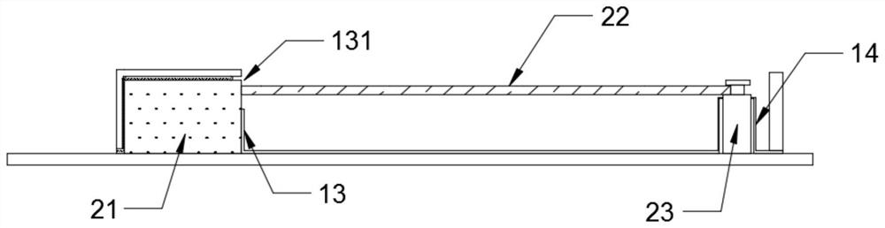
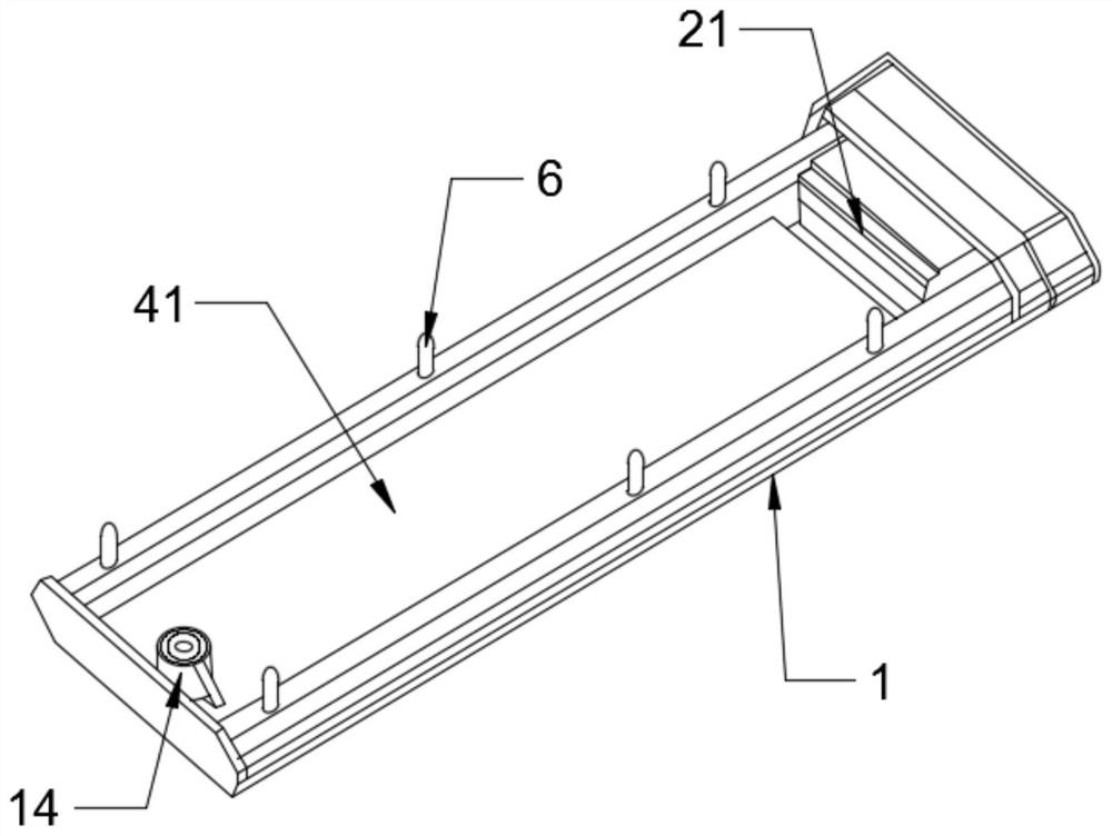
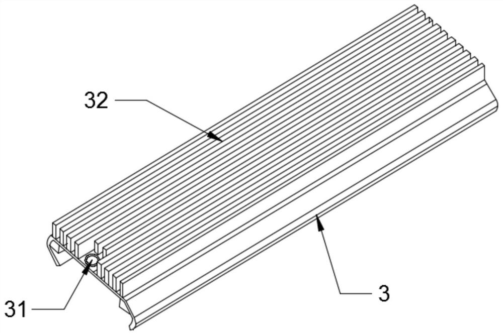
[0020] Such as Figure 1 to 5 The protective fixing structure of a computer hardware, including housing 1, the housing is integrally long, and the length across the solid-state hard disk slot and solid state hard drive fixed column, where, in order to facilitate the fixation of the housing, One side of the housing 1 is provided for a first cavity 11 for a solid state hard disk slot 21 and a bottom opening, and a second cavity for placing the solid state hard disk PCB plate 22 and the top opening. 12. The width and length of the first cavity here is grea...


PUM


Abstract

The invention relates to a protective fixing structure for computer hardware. The protective fixing structure comprises a shell, a first cavity is formed in one side of the shell, a second cavity is formed in the other side of the shell, a baffle is arranged between the first cavity and the second cavity, and a through hole is formed in the baffle; and one side, far away from the first cavity, of the second cavity is provided with a fixing cylinder which protrudes upwards and is used for sleeving the fixing column, the upper cover of the shell is provided with a cover plate for sealing the second cavity, a bolt hole is concentrically formed in the position, close to the fixing cylinder, of the cover plate, and cooling fins are further distributed on the cover plate. A relatively closed space can be formed by the shell and the cover plate, dust and moisture in a case are prevented from continuously damaging the solid state disk PCB, the stability and reliability of the solid state disk are guaranteed, meanwhile, the solid state disk PCB under the protection fixing structure is fixed in a normal mode, and the weight of the shell and the cover plate is not pressed on the PCB of the solid state disk, so that the deformation of the PCB is not affected, and the data security in the solid state disk is ensured.

Description

Technical field [0001] The present invention belongs to the field of computer technology, in particular the field of protective fixing structures of computer hardware. Background technique [0002] Computer hardware refers to a general term for various physical devices composed of electronics, mechanical, and photoelectric elements, etc. in the computer system; these physical devices constitute an organic overall to provide a material basis for computer software operations; computer hardware typically includes memory , Motherboard, graphics card, CPU, hard disk, etc., where the hard disk is an indispensable part of computer storage, with the popularity of solid state drives, the solid state drive of the M.2 interface is subject to the advantage of its size, powerful performance, etc. Favored, in which NVME solid state drives are excellent in reading and writing performance, especially by the favorite of high-end players, the main body of M2 solid state drives in NVME protocols is...

Claims


Application Information

Patent Timeline
IPC IPC(8): G11B33/14G11B33/08
CPCG11B33/1446G11B33/1413G11B33/1426G11B33/1486G11B33/08Y02D10/00
Inventor 刘晓飞
Owner ANQING NORMAL UNIV
Why Eureka
Try Eureka