
Heat dissipation device

A heat dissipation device and heat pipe technology, applied in the direction of heat sinks, indirect heat exchangers, heat exchange equipment, etc., can solve the problems of small area, dissipate heat, and no longer meet the heat dissipation requirements, so as to improve the speed of heat diffusion and increase the uniformity The effect of temperature characteristics

Pending Publication Date: 2021-06-18
COOLER MASTER CO LTD
View PDF0 Cites 0 Cited by
  • Summary
  • Abstract
  • Description
  • Claims
  • Application Information

AI Technical Summary

Problems solved by technology

However, the traditional simple aluminum extruded and die-cast cooling fins have extremely limited heat dissipation area due to mechanical processing, and the area for exchanging heat with the surrounding air is not large. Even with a fan, the heat cannot be dissipated in time and fully. This kind of heat dissipation fin no longer meets the heat dissipation requirements of current electronics manufacturers

Method used


Image

  • Heat dissipation device
  • Heat dissipation device
  • Heat dissipation device

Examples


Embodiment Construction

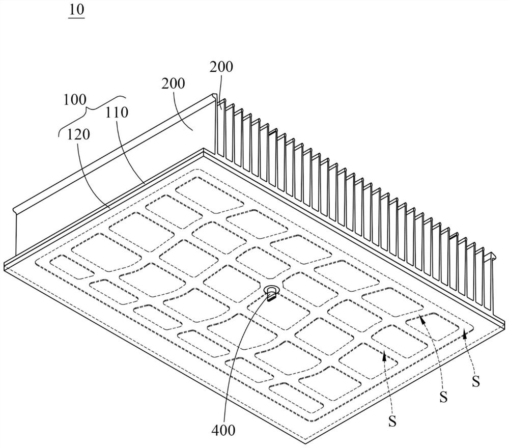
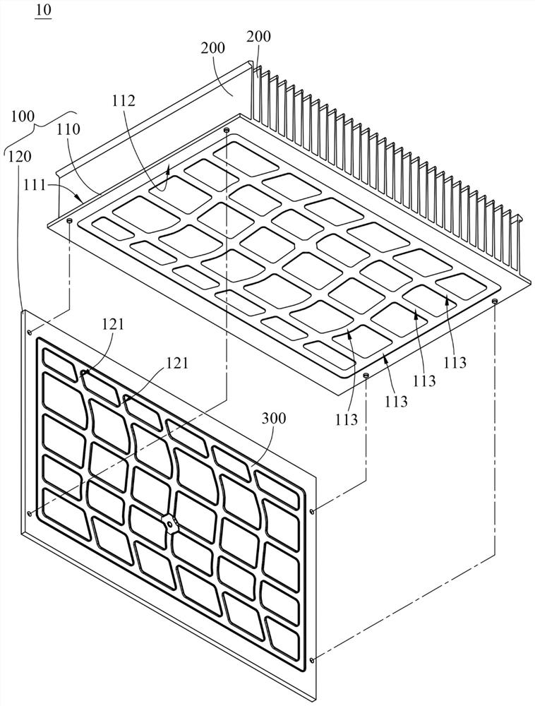
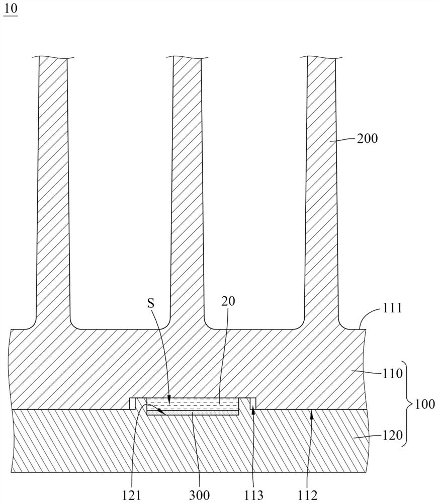
[0040] see Figure 1 to Figure 3A . figure 1 It is a three-dimensional schematic diagram of the heat dissipation device according to the first embodiment of the present invention. figure 2 for figure 1 The decomposition diagram. Figure 3A for figure 1 sectional schematic diagram.

[0041] The heat sink 10 of this embodiment is used for filling a phase change fluid 20 . The phase change fluid 20 is, for example, water, alcohol, refrigerant, etc. The choice of the phase change fluid 20 can be determined by the material of the heat sink 10 itself or the working temperature of the heat source (not shown). For example, the acceptable working temperature of the heat source is 80°C to 100°C, and the vaporization temperature of the phase change fluid 20 is 80°C to 100°C.

[0042] The heat sink 10 includes a base 100 , a plurality of fins 200 and a plurality of capillary structures 300 . The base 100 has a plurality of internal flow channels S, and these internal flow channels...


PUM


Abstract

The invention discloses a heat dissipation device, which is used for filling a phase change fluid. The heat dissipation device comprises a base part, a plurality of fin parts and at least one capillary structure. The base part is provided with at least one internal flow channel. The internal flow channel is used for filling phase change fluid. The fin parts are connected to one side of the base part. The at least one capillary structure is located in the at least one internal flow channel. By forming the internal flow channel on the base part and forming the capillary structure on the wallsurface of the internal flow channel on the base part, the heat diffusion speed of the heat dissipation device is improved, and the heat generated by the heat source can be wholly and uniformly discharged by the heat dissipation device.

Description

technical field [0001] The invention relates to a heat dissipation device, in particular to a heat dissipation device with an internal flow channel and a capillary structure. Background technique [0002] As the operating frequency and speed of electronic components continue to increase, the heat generated per unit volume of electronic components increases accordingly. However, due to the limitation of mechanical processing, the traditional simple aluminum extruded and die-cast cooling fins have extremely limited heat dissipation area, and the area for exchanging heat with the surrounding air is not large. This heat dissipation fin no longer meets the heat dissipation requirements of current electronics manufacturers. Contents of the invention [0003] The purpose of the present invention is to provide a heat dissipation device, so as to improve the heat dissipation efficiency of the heat dissipation device. [0004] A heat dissipation device disclosed in an embodiment o...

Claims


Application Information

Patent Timeline
IPC IPC(8): H01L23/367H01L23/427H01L23/473
CPCH01L23/3672H01L23/427H01L23/473F28D15/0233F28D15/0275F28F3/048F28F3/027F28F2215/10H05K7/20336
Inventor 林家羽郑善尹刘建廷
Owner COOLER MASTER CO LTD
Learn More