

Snakelike flow field structure
A serpentine and flow field technology, which is applied in the field of fuel cells, can solve the problems that products cannot be discharged in time, heat cannot be dissipated in time, and battery performance is degraded.
- Summary
- Abstract
- Description
- Claims
- Application Information
AI Technical Summary
Problems solved by technology
Method used
Image

Examples
Embodiment 1
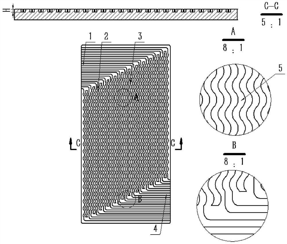
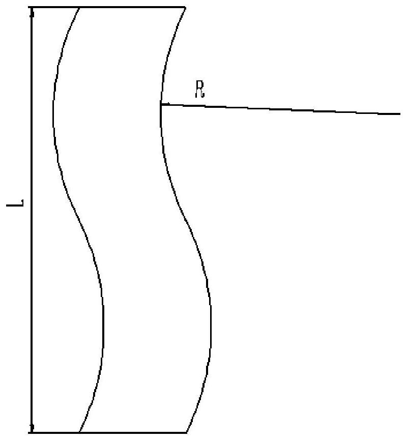
[0027] A serpentine flow field structure, the central area of the flow field structure is provided with a plurality of serpentine ridges II2, the plurality of serpentine ridges II2 are arranged in parallel, and the serpentine ridge II2 is composed of a plurality of s-shaped units 5 at the head and tail Connecting structure, the linear distance L between the two ends of the s-shaped unit 5 is 2mm, the arc radius R of the s-shaped unit 5 is 2mm, the height H of the s-shaped unit 5 is 0.4mm and each The heights H of the s-shaped units 5 are all the same, and a serpentine gas flow channel 3 is formed between adjacent serpentine ridges II2;
[0028] The flow field structure is provided with a plurality of ridges I1, and the plurality of ridges I1 are arranged in parallel, and a gas inlet channel is formed between adjacent ridges I1, and the gas inlet channel communicates with the serpentine gas flow channel 3;
[0029] The flow field structure is provided with a plurality of ridg...
Embodiment 2
[0032] A serpentine flow field structure, the central area of the flow field structure is provided with a plurality of serpentine ridges II2, the plurality of serpentine ridges II2 are arranged in parallel, and the serpentine ridge II2 is composed of a plurality of s-shaped units 5 at the head and tail connected, the linear distance L between the two ends of the s-shaped unit 5 is 2 mm, the arc radius R of the s-shaped unit 5 is 1.5 mm, the height H of the s-shaped unit 5 is 0.4 mm, and each The height H of each s-shaped unit 5 is the same, and a serpentine gas flow channel 3 is formed between adjacent said serpentine ridges II2;
[0033] The flow field structure is provided with a plurality of ridges I1, and the plurality of ridges I1 are arranged in parallel, and a gas inlet channel is formed between adjacent ridges I1, and the gas inlet channel communicates with the serpentine gas flow channel 3;
[0034] The flow field structure is provided with a plurality of ridges III...
Embodiment 3
[0037] A serpentine flow field structure, the central area of the flow field structure is provided with a plurality of serpentine ridges II2, the plurality of serpentine ridges II2 are arranged in parallel, and the serpentine ridge II2 is composed of a plurality of s-shaped units 5 at the head and tail Connecting structure, the linear distance L between the two ends of the s-shaped unit 5 is 4mm, the arc radius R of the s-shaped unit 5 is 1.5mm, the height H of the s-shaped unit 5 is 0.4mm and each The height H of each s-shaped unit 5 is the same, and a serpentine gas flow channel 3 is formed between adjacent said serpentine ridges II2;
[0038] The flow field structure is provided with a plurality of ridges I1, and the plurality of ridges I1 are arranged in parallel, and a gas inlet channel is formed between adjacent ridges I1, and the gas inlet channel communicates with the serpentine gas flow channel 3;
[0039] The flow field structure is provided with a plurality of rid...
PUM
| Property | Measurement | Unit |
|---|---|---|
| Arc radius | aaaaa | aaaaa |
| Height | aaaaa | aaaaa |
Abstract
Description
Claims
Application Information