Waste water denitrification nitrogen removal reactor

A denitrification and reactor technology, applied in chemical instruments and methods, anaerobic digestion treatment, biological water/sewage treatment, etc., can solve the problems of easy clogging and high energy consumption, and achieve clogging prevention, energy consumption reduction and mass transfer good effect

Pending Publication Date: 2019-01-01
ZHEJIANG HI TECH ENVIRONMENTAL TECH
View PDF0 Cites 3 Cited by
  • Summary
  • Abstract
  • Description
  • Claims
  • Application Information

AI Technical Summary

Problems solved by technology

[0005] In order to overcome the defects of high energy consumption and easy blockage in the operation process of the prior art, and realize the effective internal circulation and fluidization of the suspended filler in the anoxic denitrification and denitrification fluidized bed reactor, the invention provides a wastewater denitrification and denitrification reactor

Method used


Image

  • Waste water denitrification nitrogen removal reactor

Examples


Embodiment 1

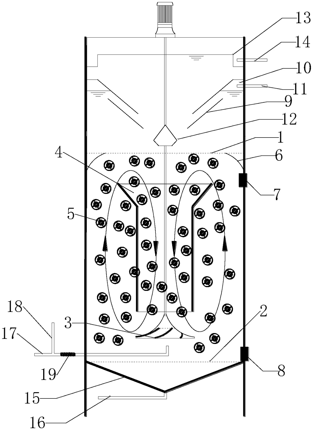
[0020] Such as figure 1 As shown, a wastewater denitrification denitrification reactor includes a three-phase separation zone, a reaction zone and a sludge discharge zone from top to bottom, the reaction zone and the three-phase separation zone are separated by the first mesh partition 1, and the reaction zone And the mud discharge area is separated by the second mesh partition 2.

[0021] A water inlet system is provided at the bottom of the reaction zone, a hyperboloid agitator 3 is installed in the center of the reaction zone, and a circular guide tube 4 is arranged above the impeller of the hyperboloid agitator 3, and the central axis of the guide tube 4 is aligned with the shaft 3 of the hyperboloid agitator Coincidentally, suspending filler 5 is added inside the reaction zone, and the first mesh partition 1 above the reaction zone is provided with a circle of diversion walls 6 along the pool wall. The suspended filler 5 realizes circulating fluidization under the synerg...

Embodiment 2

[0030] A waste water denitrification and denitrification reactor, with the production waste water of a polysilicon enterprise as the treatment object, carried out the pilot test of denitrification and denitrification. The filling rate of the suspended filler in the reactor is 50%, and the reactor device runs continuously for 24 hours, and industrial methanol is added as a carbon source. The pilot experiment was carried out continuously for 3 months, and some experimental data are shown in Table 1.

[0031] Table 1 Pilot test data of wastewater denitrification and denitrification

[0032] serial number

[0033] During the pilot test, the reaction device operated stably and basically had no failures. The experimental data shows that the influent TN is about 500 mg / L, which is reduced to less than 10 mg / L after treatment, and the removal rate reaches more than 98%, which meets the requirements of the discharge standard. After calculation, the total nitrogen removal vo...


PUM

PropertyMeasurementUnit
Slopeaaaaaaaaaa

Abstract

The invention discloses a waste water denitrification nitrogen removal reactor. The waste water denitrification nitrogen removal reactor comprises a three-phase separation area, a reaction area and asludge discharging area, wherein the three areas are separated by virtue of a mesh separation plate. A two-curved-surface stirrer is installed on the center of the reaction area, a guide cylinder is arranged above an impeller of the two-curved-surface stirrer, the axis of the guide cylinder is overlapped with the axis of the two-curved stirrer, suspension filler is fed into the reaction area, andthe mesh separation plate above the reaction area is provided with a circle of arc guide wall along the tank wall. Under the synergistic effect of the two-curved-surface stirrer, the guide cylinder, the arc guide wall and the mesh separation plate, no dead corner exists inside the reactor, the filler can be orderly and circularly fluidized inside the tank body, the filler and the waste water are completely mixed, the mass transfer effect is good, a biological membrane attached on the surface of the suspension filler sufficiently contacts the waste water, and the stable and efficient operationof the waste water denitrification nitrogen removal reactor can be ensured. In addition, the two-curved-surface stirrer is used for substituting a traditional water distribution device, so that the system blocking can be avoided, and the energy consumption can also be reduced.

Description

technical field [0001] The invention relates to water treatment equipment, in particular to a wastewater denitrification and denitrification reactor. Background technique [0002] On April 9, 2018, the Ministry of Ecology and Environment issued the "Notice on Strengthening the Prevention and Control of Nitrogen and Phosphorus Pollution from Stationary Pollution Sources". The notice pointed out that the situation of water pollution prevention and control across the country is facing new changes, and nitrogen and phosphorus pollution in some areas has become the main problem of water pollution prevention and control, and has become a prominent bottleneck affecting the improvement of water quality in river basins. There are many sources of nitrogen and phosphorus pollution, and stationary pollution sources are still an important source, and in some places they are still the main source. The notice also clarifies that 18 industries, including centralized sewage treatment and la...

Claims


Application Information

Patent Timeline
IPC IPC(8): C02F3/28
CPCC02F3/28C02F3/2866
Inventor 许海亮郑元武余华东陈新才林彤晖周杰楼洪海
Owner ZHEJIANG HI TECH ENVIRONMENTAL TECH
Why Eureka
Try Eureka