A control method of a soldering device for an enameled wire lead

An enameled wire lead wire and control method technology, which is applied to tin feeding devices, welding equipment, manufacturing tools, etc., can solve the problems of dull surface of solder joints, slow rise of tin liquid, and insurmountable immersion soldering, so as to prevent tin-copper fusion Difficult, improve brightness, avoid the effect of frying tin

Active Publication Date: 2022-04-19
厦门瑞熠自动化系统有限公司
View PDF0 Cites 0 Cited by
  • Summary
  • Abstract
  • Description
  • Claims
  • Application Information

AI Technical Summary

Problems solved by technology

[0003] Most of the tin soldering processes used now use dip soldering, but dip soldering has always had many insurmountable problems
Difficulty in tinning: need paint remover, lead or flux; heat radiation, heat conduction damage to the skeleton; tin beads splashed on the wire package; tin dust and tin slag; tin liquid climbs slowly; tin tip; tin pot is easy Corrosion; the surface of the solder joint is not bright; the lead wire is torn off during the cooling and shrinkage of the tin
However, soldering iron soldering is not widely used because of the sudden drop in the heat absorption temperature of molten tin, which makes the tin temperature unable to vaporize the paint film, resulting in virtual soldering.

Method used


Image

  • A control method of a soldering device for an enameled wire lead
  • A control method of a soldering device for an enameled wire lead
  • A control method of a soldering device for an enameled wire lead

Examples


Embodiment Construction

[0036] In order to facilitate the understanding of those skilled in the art, the structure of the present invention will be further described in detail with the embodiments in conjunction with the accompanying drawings:

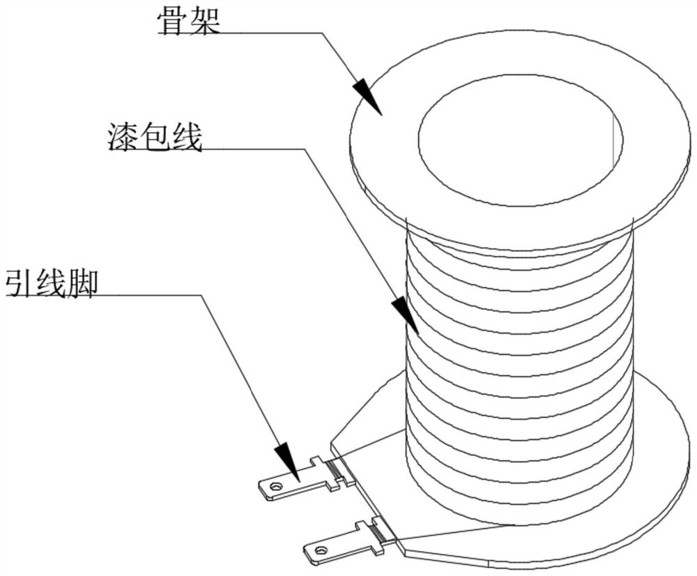
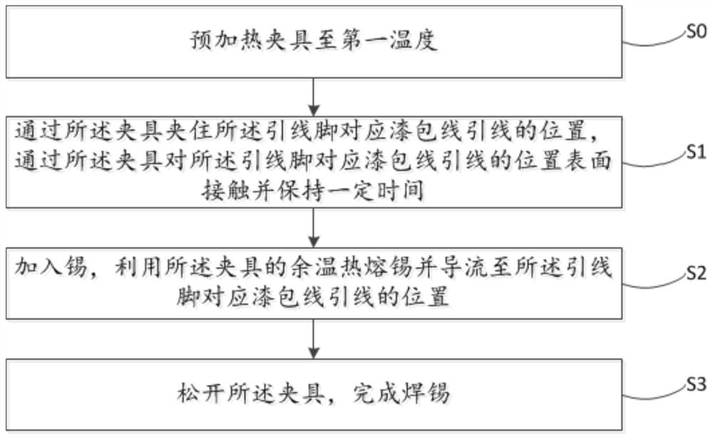
[0037] A method for soldering an enameled wire lead, wherein the enameled wire lead is wound around the end of the lead foot close to the skeleton, comprising the following steps:

[0038] S0, heat the fixture to the vaporization temperature of the paint film; specifically, in this embodiment, the fixture is preheated to 450°C, which is higher than the melting temperature of tin at 280°C, and at the same time, sufficient heat energy can be stored in the fixture without scalding the skeleton , In other embodiments, the fixture may also be preheated to 500° C., and in this embodiment, the fixture is made of metal, which has the functions of heat conduction and heat storage.

[0039] S1, using the clamp to clamp the position of the lead pin corresponding to the ...


PUM


Abstract

The invention relates to a method for controlling a soldering device for enameled wire leads, comprising the following steps: S1, providing a soldering device for enameled wire leads; S2, placing skeletons in parallel on the skeleton positioning mechanism; S3, controlling the heating mechanism to heat the fixture to The first temperature; S4, control the first driving cylinder to drive the clamp to close and hold one of the lead pins of the frame corresponding to the position of the enameled wire lead, and keep it for the first time; S5, control the reel to pull out the tin wire from the reel and send it Enter the tin feeding conduit, make the tin wire contact the clamping part, use the residual temperature of the clamping part to melt the tin and divert it to the position of the lead pin corresponding to the lead wire of the enameled wire; S6, control the first driving cylinder to drive the clamping part Loosen; S7, control the second driving cylinder to drive the mounting plate to move laterally, so that the clamping part corresponds to the position of the other lead pin of the frame corresponding to the lead wire of the enameled wire, and repeats steps S3-6.

Description

technical field [0001] The invention relates to the field of soldering of enameled wire leads, in particular to a control method of a soldering device for enameled wire leads. Background technique [0002] Soldering has been a main way of conducting and fixing the enameled wire coil and the lead pin. It is characterized by low cost, enameled wire diameter is not easy to change, and good stability. [0003] Most of the tin soldering processes used now use dip soldering, but dip soldering has always had many insurmountable problems. Difficulty in tinning: need paint remover, lead or flux; heat radiation, heat conduction damage to the skeleton; tin beads splashed on the wire package; tin dust and tin slag; tin liquid climbs slowly; tin tip; tin pot is easy Corrosion; the surface of the solder joint is not bright; the lead wire is torn off during the cooling and shrinkage of the tin. However, soldering iron soldering is not popularized because of the sudden drop in the heat a...

Claims


Application Information

Patent Timeline
Patent Type & Authority Patents(China)
IPC IPC(8): B23K1/00B23K3/00B23K3/06
CPCB23K1/00B23K1/0008B23K3/00B23K3/06B23K3/063
Inventor 王建
Owner 厦门瑞熠自动化系统有限公司
Why Eureka
Try Eureka