A kind of high binding force electroplating equipment and its application method

An electroplating equipment and bonding force technology, applied in the field of high-bonding force electroplating equipment, can solve the problems of economic loss, rough coating, insufficient coating bonding force, etc., and achieve the effects of improving bonding force, preventing backflow, and improving filtering effect.

Active Publication Date: 2022-01-07
JIANGSU LIANGYOU STEEL WIRE CO LTD
View PDF3 Cites 0 Cited by
  • Summary
  • Abstract
  • Description
  • Claims
  • Application Information

AI Technical Summary

Problems solved by technology

[0004] Defects in electroplating production are inevitable, and frequent occurrence of defects will affect production progress and product qualification rate, resulting in economic losses
Insufficient bonding force of the plating layer is the most common adverse phenomenon. The reason is that the anode will produce various solid impurities and dross, making the plating layer rough, loose, and porous. The measures taken by the current electroplating process are to put an anode bag on the anode, but the anode After the bag has been used for a long time, impurities will accumulate on the bag, which will block the flow of the electroplating solution and directly affect the quality of electroplating.

Method used


Image

  • A kind of high binding force electroplating equipment and its application method
  • A kind of high binding force electroplating equipment and its application method
  • A kind of high binding force electroplating equipment and its application method

Examples


Embodiment

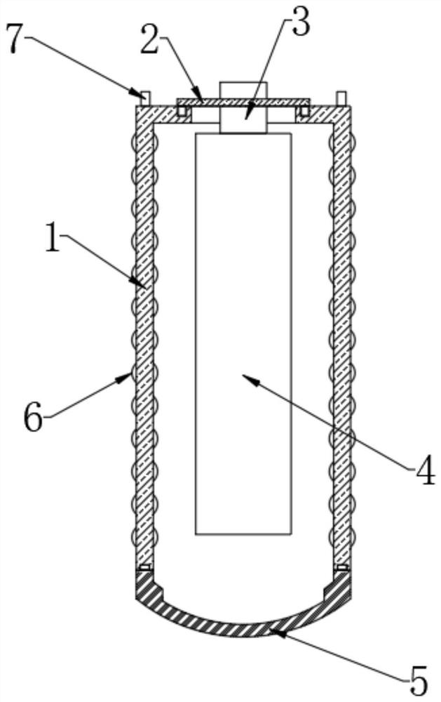
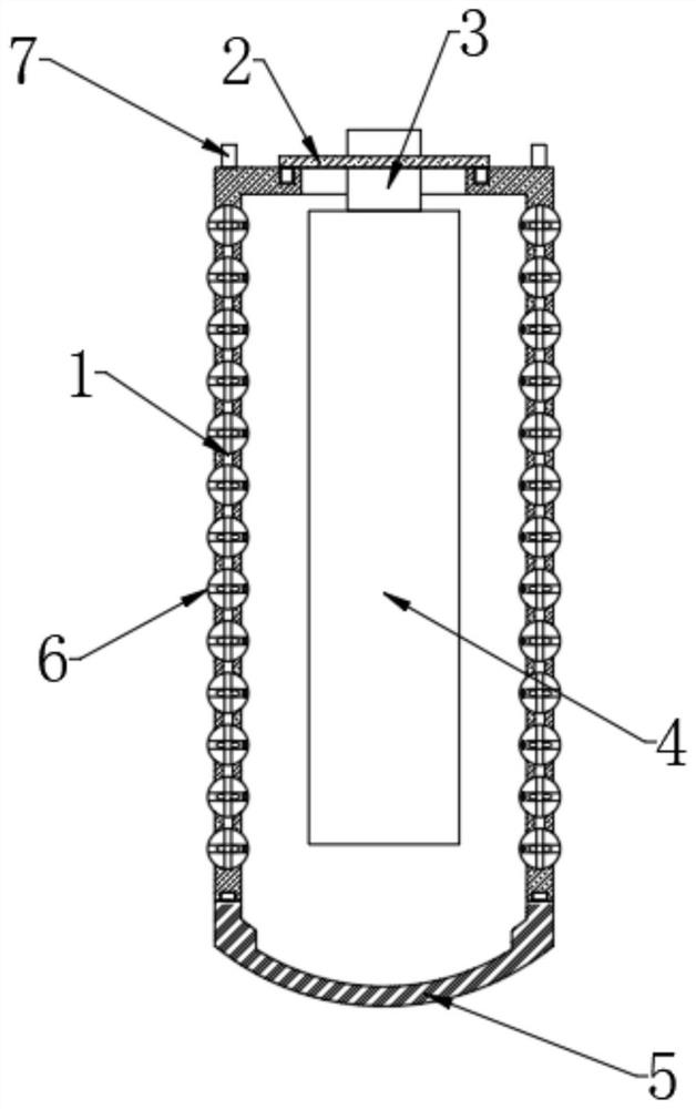
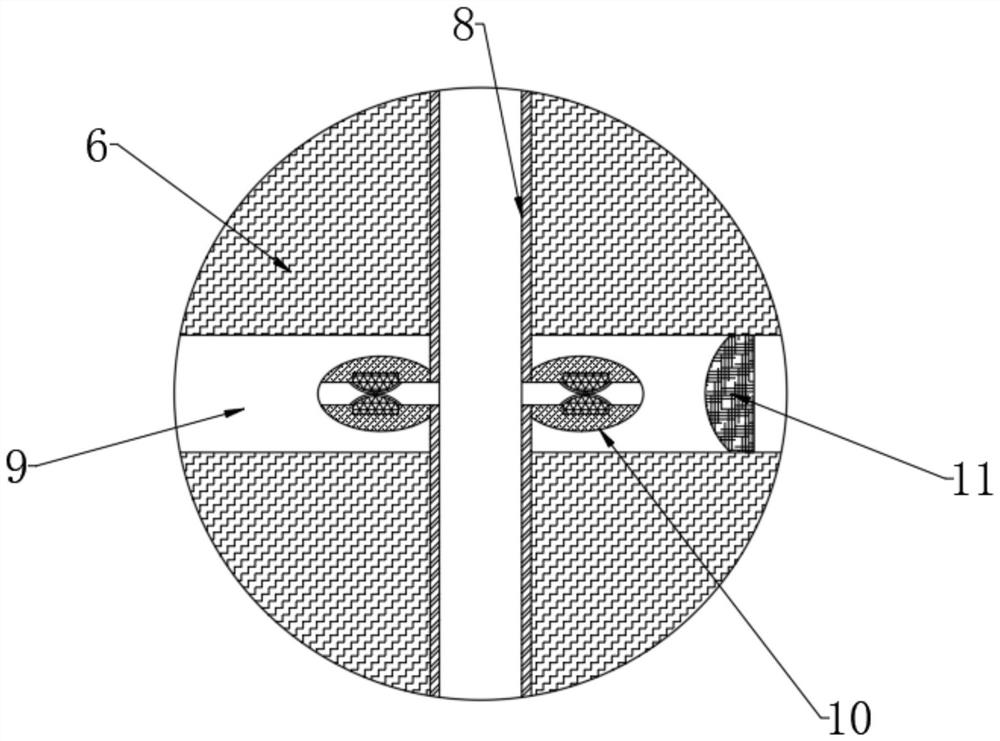
[0046] see Figure 1-7 , a high-binding force electroplating device, including a choke case 1 and an anode 4, see Figure 1-2 , the upper end of the choke case 1 is provided with an opening, and the opening is connected with a sealing plate 2, the sealing plate 2 is fixedly connected with a clamp 3, and the anode 4 is clamped at the lower end of the clamp 3, and the lower end of the choke case 1 is connected with a connector. The bottom shell 5, the sealing plate 2, the bottom shell 5 and the choke shell 1 are all connected by magnetic adsorption to facilitate installation and disassembly, and a gasket is provided at the joint to prevent impurities from entering through the gap Into the external electroplating solution, the side wall of the choke case 1 is fixedly embedded with a plurality of filter balls 6, and the inner wall of the choke case 1 is fixedly embedded with a vent pipe 8 passing through a plurality of filter balls 6, and the upper end side of the choke case 1 Th...


PUM


Abstract

The invention discloses a high-binding force electroplating equipment and a method for using the same, belonging to the field of electroplating. A high-binding electroplating equipment includes a choke case and an anode. The plate and the sealing plate are fixedly connected with a jig, and the anode is clamped at the lower end of the jig. In this scheme, a choke shell is placed on the outside of the anode to prevent the agitation from affecting the settlement of solid impurities. The double-layer filter improves the filtering effect of solid impurities. , to prevent impurities from moving to the plated parts and cause the coating to be rough, loose, porous, and effectively improve the bonding force between the coating and the anode. The filter screen is deformed and shaken by the agitation of the gas to the plating solution, and the impurities adhered to the filter screen are removed. It realizes self-cleaning and effectively improves the filtering effect. The gas release control part is used to prevent the electroplating solution from flowing backward into the vent tube, and the elastic force and gas compressibility are used to realize self-closing, which is convenient for the gas to enter.

Description

technical field [0001] The invention relates to the field of electroplating, and more specifically relates to a high-binding force electroplating equipment and a method for using the same. Background technique [0002] Electroplating is the process of plating a thin layer of other metals or alloys on the surface of certain metals using the principle of electrolysis. It is a process of using electrolysis to attach a layer of metal film to the surface of metal or other material parts to prevent metal oxidation ( Such as rust), improve wear resistance, electrical conductivity, reflective properties, corrosion resistance (copper sulfate, etc.) and enhance the appearance. During electroplating, the plated metal or other insoluble materials are used as the anode, and the workpiece to be plated is used as the cathode, and the cations of the plated metal are reduced on the surface of the workpiece to be plated to form a coating. In order to eliminate the interference of other catio...

Claims


Application Information

Patent Timeline
Patent Type & Authority Patents(China)
IPC IPC(8): C25D17/00C25D21/06C25D21/12
CPCC25D17/00C25D21/06C25D21/12
Inventor 曾鹏
Owner JIANGSU LIANGYOU STEEL WIRE CO LTD
Why Eureka
Try Eureka