Transverse and longitudinal integrated power bogie with axle boxes capable of measuring temperature

A power bogie, integrated technology, applied in the direction of bogie, axle box, axle box installation, etc., can solve the problems of increasing the structural size and turning radius of the bogie, time-consuming and labor-intensive, narrow inner ring of the bearing, etc., so as to facilitate independent replacement and overhaul, reduce manufacturing costs, and improve structural strength

Pending Publication Date: 2021-06-25
CRRC CHANGCHUN RAILWAY VEHICLES CO LTD
View PDF2 Cites 0 Cited by
  • Summary
  • Abstract
  • Description
  • Claims
  • Application Information

AI Technical Summary

Problems solved by technology

However, the layout position of the motor hanger t and the gear box hanger u of this installation method that relies on the integral beam body g or the well-shaped beam body h and is completely rigidly connected with the motor hanger t and the gear box hanger u And welding manufacturing process not only puts forward higher requirements on the structural strength and symmetry accuracy of the beam body, but also occupies most of the space inside the conventional frame, resulting in the lack of sufficient axle box layout space inside the existing bogie. As a result, the typical primary suspension device can only be arranged at the two ends of the axle, which not only increases the risk of damage to the axle box, but also increases the overall structural size and turning radius of the bogie, which is not conducive to the improvement of its minimum curve passing capacity. And because the lifting lugs of the casing of the traction motor r are non-removable rigid structures, it interferes with the frame and the gearbox structure and blocks each other, so that the traction motor r cannot be removed from the bottom of the car body directly through the maintenance ditch, but must be used on a truck Only by separating the compartment above the frame from the frame can the traction motor r be withdrawn from the frame, which greatly increases the difficulty of motor maintenance and replacement
At the same time, the rigid connection of the motor hanger t and the gearbox hanger u also leads to the lack of sufficient vibration reduction protection system for the traction motor r and the gearbox s, which in turn makes the auxiliary structures such as the anti-snake shock absorber and the anti-rolling torsion bar n Installation becomes an indispensable and necessary supplement
[0007] In addition, different train design speed requirements or different side beam structures will also have a great impact on the layout space and structural form of the primary suspension device and secondary suspension device, as well as the motor and gearbox, often resulting in the old primary suspension. The layout scheme of the suspension device or the secondary suspension device cannot meet the requirements of the installation position and the vibration reduction index, so it is necessary to overthrow the old reference scheme and make a design improvement with a new concept
[0008] like Figure 4 to Figure 6 As shown, the existing large gear s-2 installed inside the shell s-1 of the snap-fit ​​and spliced ​​gearbox is directly press-fitted with the bearing outer ring s-3-2 on the large gear bearing s-3 to form a coaxial fixed connection Interference fit, the gear box installation shaft section d-1 on the axle d is directly press-fitted with the large gear bearing inner ring s-3-1 on the large gear bearing s-3 to form a coaxial fixed interference fit, the process The coaxial fixed connection form of the interference fit makes the gearbox installation shaft section d-1, the gearbox bearing s-3 and the large gear s-2 become an inseparable whole, and, due to the snap-fit ​​spliced ​​gearbox shell s- 1 has low structural strength, and it cannot be directly used as the focus point of the withdrawal baffle on the wheel shaft withdrawal press. Moreover, the bearing inner ring of the existing large gear bearing s-3 is too narrow, resulting in that even if the wheel shaft withdrawal pressure The on-board unloading baffle is refitted into a multi-jaw chuck and inserted into the gear box through the axle through hole on the axial side wall of the gear box. However, due to the lack of sufficient radial force points, it is still impossible to reliably clamp the large The inner ring s-3-1 of the gear bearing implements the radial withdrawal blocking force, so that the withdrawal of the axle cannot be directly implemented, and then when the subsequent maintenance of the axle d or the large gear s-2 must be buckled and spliced The gearbox casing s-1 is the first to release the original splicing and fastening state, and the axle d, the large gear s-2 and the large gear bearing s-3 that are coaxially fixed with it are removed from the frame as a whole. Then transfer to the axle unloading press to complete the unloading and replacement operation
The process of this method is cumbersome, time-consuming and labor-intensive, and it is impossible to remove and replace the axle d independently without removing the large gear s-2 from the snap-fit ​​spliced ​​gearbox casing s-1, and it is also impossible to maintain the buckle. Under the premise that the shell s-1 of the spliced ​​gearbox is in the fastened state, pull out the axle d separately and directly repair the large gear s-2 in the shell s-1 of the gearbox from the hole left after the axle d is removed. and lubrication maintenance

Method used


Image

  • Transverse and longitudinal integrated power bogie with axle boxes capable of measuring temperature
  • Transverse and longitudinal integrated power bogie with axle boxes capable of measuring temperature
  • Transverse and longitudinal integrated power bogie with axle boxes capable of measuring temperature

Examples


Embodiment Construction

[0060] The present invention will be described in further detail below in conjunction with the accompanying drawings.

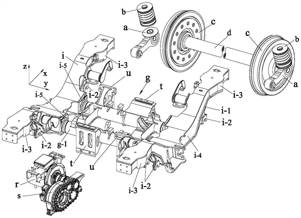
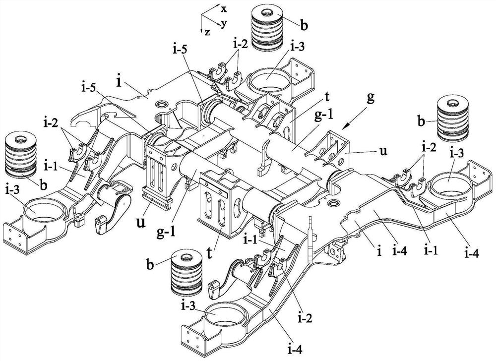
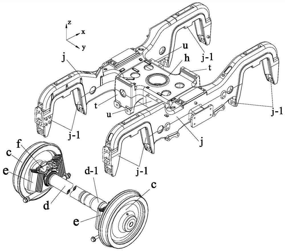
[0061] like Figure 7 to Figure 19 As shown, the horizontally and vertically integrated power bogie with temperature-measuring axleboxes of the present invention includes: a wheel set device composed of wheels and axles, a horizontally and vertically integrated interconnection frame, four ring-shaped damping axleboxes, an easy-to-return Shaft gearbox, side beam single-point suspension motor; horizontal and vertical integrated interconnection frame includes two horizontal and vertical integrated frames that are rotationally symmetrical to each other, and each horizontal and vertical integrated frame includes an integrally formed integrated side beam 1-1 and the integrated beam 1-2; the integrated side beam 1-1 includes the middle section of the side beam 1-1-1 which is the connecting part of the two bird wings and is at a lower position and two symmetrically f...


PUM


Abstract

The invention discloses a transverse and longitudinal integrated power bogie with axle boxes capable of measuring temperature, and belongs to the field of railway vehicle power bogie devices. The transverse and longitudinal integrated power bogie comprises a transverse and longitudinal integrated interconnection framework, four annular vibration reduction axle boxes, an easy-shaft-withdrawing gearbox and a side beam single-point suspension type motor. The transverse and longitudinal integrated interconnection framework comprises two transverse and longitudinal integrated frameworks, and each transverse and longitudinal integrated framework comprises an integrated side beam and an integrated cross beam which are integrally formed; and the integrated side beam comprises a side beam middle section serving as two wing connecting parts and located at a low position and two wing-shaped side beam cantilever sections symmetrically and fixedly connected to the two ends of the side beam middle section. According to the invention, enough operation space is reserved for disassembly and maintenance of a gearbox and a motor, and the assembly and disassembly scheme of the motor is greatly optimized; and after four fastening bolts of the motor flexible suspension rubber nodes and the side beam end motor suspension rubber nodes are dismantled respectively, the side beam single-point suspension type motor can be directly and independently dismantled from the lower portion of a vehicle body through and overhaul trench, and the motor overhaul convenience is greatly improved.

Description

technical field [0001] The invention belongs to the field of rail vehicle power bogie devices, and in particular relates to a horizontally and vertically integrated power bogie with a temperature-measuring axle box. Background technique [0002] The design of rail train bogies not only needs to comprehensively consider the structural strength of the main body of the load-bearing frame, the effect of various auxiliary damping components such as anti-snake dampers, and the installation method of the braking mechanism, but also needs to be aimed at different According to the train's theoretical speed, bearing load, minimum curve curvature and wind, snow and flying rocks and other road conditions, comprehensively design the suspension mode of the power bogie motor, the placement position of the axle box on the wheel axle, the motor and its gearbox There are many factors such as the layout space, the structural form and layout space of the primary suspension and the secondary sus...

Claims


Application Information

Patent Timeline
Patent Type & Authority Applications(China)
IPC IPC(8): B61F5/52B61C9/50B61F5/30B61F15/20B61K9/06
CPCB61C9/50B61F5/305B61F5/52B61F15/20B61K9/06
Inventor 张文康薛世海洪海峰李国栋
Owner CRRC CHANGCHUN RAILWAY VEHICLES CO LTD
Why Eureka
Try Eureka