Freight unmanned aerial vehicle with obstacle avoidance mechanism
A technology for unmanned aerial vehicles and warehouses, applied in the field of unmanned aerial vehicles, can solve the problems of easy intrusion, reduced image clarity, and the camera does not have waterproof and vapor functions, and achieves the effect of preventing downward penetration and increasing the contact area.
- Summary
- Abstract
- Description
- Claims
- Application Information
AI Technical Summary
Problems solved by technology
Method used
Image
Examples
Embodiment 1
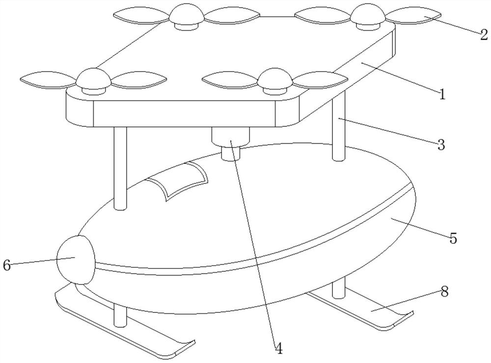
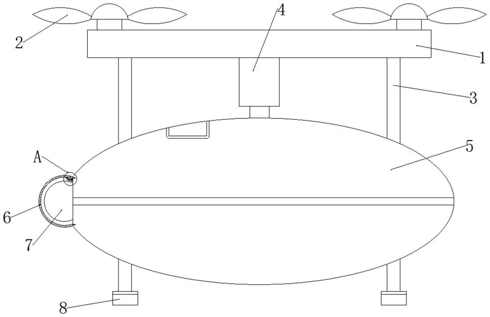
[0040] see Figure 1-3 , in an embodiment of the present invention, a cargo drone with an obstacle avoidance mechanism includes a body 1, a propeller 2, a support rod 3, a cylinder 4, a cargo compartment 5, an obstacle avoidance camera 7 and a foot plate 8, and the left end of the cargo compartment 5 The central part of the head is located at the outer end of the obstacle avoidance camera 7 and is fixedly installed with a waterproof assembly 6 that can prevent the infiltration of water vapor;
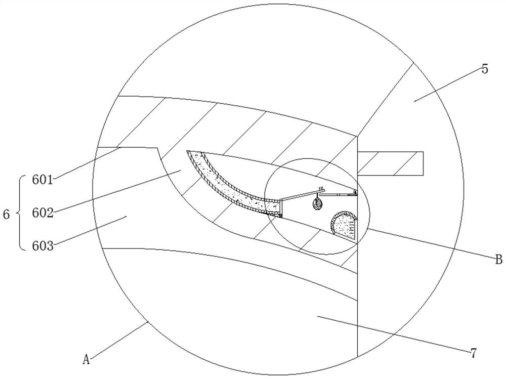
[0041]The waterproof assembly 6 is composed of a waterproof cover 601 , a dewatering assembly 602 capable of absorbing water vapor, and a large cavity 603 .
[0042] In the embodiment of the present invention, the waterproof cover 601 has a hemispherical appearance and is fixedly installed in the center of the left end head of the warehouse 5 in a sealed manner. Component 602, a large cavity 603 is provided between the interior of the waterproof cover 601 and the obstacle avoidance cam...
Embodiment 2
[0045] see image 3 and Figure 4 , in the embodiment of the present invention, the dewatering component 602 is composed of a water retaining strip 6021, a small cavity 6022, a water measuring component 6023 that can monitor whether water vapor enters, a material storage channel 6024, a discharge component 6025 that can replenish dewatering materials, The lifting assembly 6026 and the V-shaped air bag 6027 are formed to facilitate the absorption of entering water vapor.
[0046] In the embodiment of the present invention, the front and rear ends of the water retaining strip 6021 of the dewatering assembly 602 are fixedly installed at the inner top position of the waterproof cover 601, and the appearance of the water retaining strip 6021 is in the shape of a letter Y on a front longitudinal section. The water retaining strip 6021 is divided into 2 layers up and down and between the inner wall and the outer surface on the left side of the warehouse 5, a small cavity 6022 is pro...
Embodiment 3
[0053] see Figure 5 , in the embodiment of the present invention, the lifting assembly 6026 is composed of an upper pull plate 60261, a piston 60262, a lower baffle 60263, a charging cylinder 60264 and several miniature balloons 60265. The right end of the bottom outer surface of the plate 60254, the bottom outer surface of the upper pull plate 60261 is fixedly equipped with a piston 60262, the left end of the bottom outer surface of the piston 60262 is fixed with a lower baffle 60263, and the appearance of the charging cylinder 60264 is in a It is elliptical in the longitudinal section of the main view, and its front and rear ends are horizontal and fixed on the inner wall of the waterproof cover 601. There is an outlet at the top and rear of the charging cylinder 60264, and a number of micro balloons 60265 are filled inside it. 60262 is in the state of closing the outlet of charging rod 60264 under normal circumstances, so as to facilitate the opening and closing of the out...
PUM
 Abstract
Description
Claims
Application Information
 - R&D
- Intellectual Property
- Life Sciences
- Materials
- Tech Scout
- Unparalleled Data Quality
- Higher Quality Content
- 60% Fewer Hallucinations
Browse by: Latest US Patents, China's latest patents, Technical Efficacy Thesaurus, Application Domain, Technology Topic, Popular Technical Reports.
© 2025 PatSnap. All rights reserved.Legal|Privacy policy|Modern Slavery Act Transparency Statement|Sitemap|About US| Contact US: help@patsnap.com


