EGR (Exhaust Gas Recirculation) valve control system and control method thereof

A technology of EGR valve and control system, applied in electrical control, engine control, fuel injection control, etc., can solve problems such as combustion deterioration, combustion phase delay, unfavorable emission stability, etc.

Pending Publication Date: 2021-06-25
FAW JIEFANG AUTOMOTIVE CO
5 Cites 2 Cited by

AI-Extracted Technical Summary

Problems solved by technology

[0004] However, as the EGR rate increases, the residual exhaust gas in the cylinder increases, the combustion phase is delayed, and the reaction speed slows down, resulting in poor combustion and poor fuel economy; at the same time, the pumping loss caused by the EGR rate will also increase fuel consumption.
[0005] There are many error factor...

Method used

Embodiments of the present invention provide a kind of realization EGR valve control system and control method thereof, mainly aiming at the closed-loop control of EGR valve opening based on air intake flow in the prior art, need model calculation total air intake, because Calculation errors will bring about inaccurate control of the EGR valve. For this reason, the embodiment of the present invention proposes to realize the opening...

Abstract

The invention relates to an EGR (Exhaust Gas Recirculation) valve control system and a control method thereof. The system comprises a controller ECU, an EGR system, a rotating speed sensor, an atmospheric temperature sensor, an atmospheric pressure sensor, a cooling liquid temperature sensor, a TMAP sensor, a Venturi flow meter differential pressure sensor and an EGR valve downstream temperature sensor. The EGR system comprises an EGR valve, an EGR intercooler and a Venturi tube; the EGR valve is connected with an exhaust pipe of the engine, and the other end of the EGR valve is connected with the EGR intercooler; the other end of the EGR intercooler is connected with the Venturi tube; the Venturi tube is connected with an air inlet pipe of the engine; and the rotating speed sensor, the atmospheric temperature sensor, the atmospheric pressure sensor, the cooling liquid temperature sensor, the TMAP sensor, the Venturi flow meter differential pressure sensor and the EGR valve downstream temperature sensor are all connected with the controller ECU. According to the EGR valve control system and the control method thereof provided by the invention, on the basis of the closed-loop control principle, PID control can be conducted on the waste gas flow according to the actual operation working condition of the engine, the opening degree of the EGR valve is adjusted in real time, emission of NOX can be effectively controlled, and meanwhile, fuel economy is improved.

Application Domain

Electrical controlInternal combustion piston engines +1

Technology Topic

Automotive engineeringIntercooler +8

Image

  • EGR (Exhaust Gas Recirculation) valve control system and control method thereof
  • EGR (Exhaust Gas Recirculation) valve control system and control method thereof
  • EGR (Exhaust Gas Recirculation) valve control system and control method thereof

Examples

  • Experimental program(1)

Example Embodiment

[0035] Example
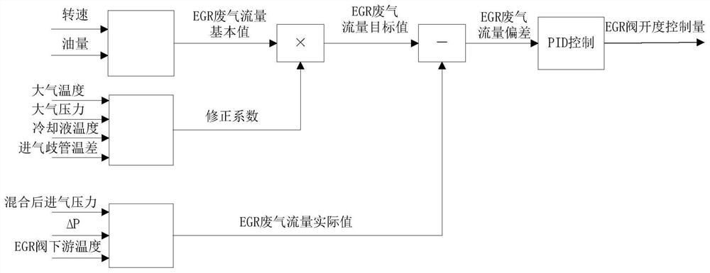
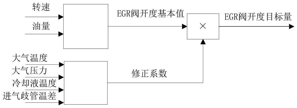
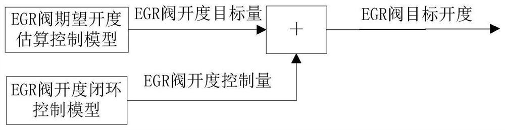
[0036] The embodiment of the present invention provides an implementation of an EGR valve control system and a control method thereof, mainly for closed loop control of the EGR valve opening degree based on the air intake flow in the prior art, requires the model to calculate the total amount of air, due to the calculation error Bringing the problem of incorrect control of EGR valve, for this purpose, the embodiment of the present invention proposes to achieve the opening degree adjustment of the EGR valve by directly closed loop control, improve the control accuracy of the EGR valve, and realize the purpose of improving engine emissions.
[0037] See Figure 4 An EGR valve control system that includes a controller ECU, an EGR system 2, a rotational speed sensor, a atmospheric temperature sensor, an atmospheric pressure sensor, a coolant temperature sensor, a TMAP sensor 3, a venturi flow meter pressure difference sensor 4 and EGR valve downstream temperature sensor 5. The EGR system 2 includes an EGR valve 21, an EGR vermicker 22, and a venturi 23; one end of the EGR valve 21 is connected to the exhaust pipe of the engine, and the other end is connected to one end of the EGR intermediate; The other end of the EGR intermediate 22 is connected to one end of the venturi tube 23; the other end of the cultu 23 is connected to the intake pipe of the engine;
[0038] The speed sensor is disposed on the engine crankshaft signal disk for measuring the engine speed signal and transmits it to the controller.
[0039] The atmospheric temperature sensor is disposed upstream of the intake pipe of the engine for measuring the engine intake temperature signal and transmits it to the controller.
[0040] The atmospheric pressure sensor is disposed upstream of the intake pipe of the engine for measuring the engine intake temperature signal and transmits it to the controller.
[0041] The coolant temperature sensor is disposed at the engine cooling line outlet position for measuring the engine coolant temperature signal and transmits it to the controller.
[0042] The TMAP sensor 3 is provided on the intake pipe for obtaining the intake manifold temperature, mixing the gas intake pressure signal and transmits to the controller.
[0043] The venturi flow meter pressure difference sensor 4 is disposed in the locust-tube 23, used to measure the pressure difference signals of the inner pressure and the venturi tubes and the controller.
[0044] The venturi flow meter pressure difference sensor preferentially adopted a high common mold pressure difference sensor to ensure a continuous high-precision output, and the error accuracy is controlled within ± 2% VCC.
[0045] The EGR valve downstream temperature sensor 5 is disposed after the EGR valve cooler 22, and is used to measure the downstream temperature signal of the EGR valve and transmit it to the controller.
[0046] A control method of an EGR valve control system, which is specifically:
[0047] See image 3 The EGR valve opening degree control amount is obtained by the EGR valve opening degree control model, and the EGR valve opening degree target obtained by the EGR valve is expected to estimate the estimation model is added to obtain the final EGR valve opening degree target.
[0048] See figure 1 The modeling method of the EGR valve opening degree closed loop control model is:
[0049] 11) According to the engine speed, the oil volume finds the EGR exhaust flow pulse spectrum to obtain the basic value of EGR exhaust flow; this pulse Figure one It is obtained by the engine multi-character feature scan point calibration test, wherein the speed and oil amount are obtained according to the controller ECU;
[0050] The EGR exhaust flow rate pulse spectrum is obtained according to the tested manner, and the EGR exhaust flow rate pulse spectrum represents the relationship between the rotational speed of the current working condition, the amount of oil, the EGR exhaust gas flow.
[0051] 12) According to the atmospheric pressure, atmospheric temperature, coolant temperature and intake manifold temperature difference Find the correction coefficient of the current desired EGR exhaust gas flow; where the atmospheric pressure, atmospheric temperature, coolant temperature It is obtained by the controller ECU; the air intake manifold is based on the manifold temperature and the deviation of the manifold reference temperature acquired according to the intake manifold temperature sensor, and the manifold reference temperature is obtained by the rotational speed and the oil volume query chart;
[0052] The EGR exhaust flow correction coefficient diagram is obtained by the experimental calibration and calculated by atmospheric pressure, atmospheric temperature, coolant temperature and intake manifold temperature differences. details as follows:
[0053] Each atmospheric temperature, atmospheric pressure, coolant temperature, intake manifold temperature, intake manifold temperature parameters are read from atmospheric temperature, atmospheric pressure, coolant temperature, intake manifold temperature sensor, and then find atmospheric temperature, atmospheric pressure, coolant temperature, respectively. The intake manifold temperature calibration pulse, obtains the atmospheric temperature correction coefficient, atmospheric pressure correction coefficient, coolant temperature correction coefficient, intake manifold temperature correction coefficient, each correction coefficient is carried out to get EGR exhaust gas under a working condition The flow correction coefficient is corrected to the EGR exhaust flow under this operating condition.
[0054] 13) According to the engine mixing, the intake pressure, the venturi tube front and rear pressure difference, and the downstream temperature of the EGR valve is calculated based on the mathematical model; wherein the engine is mixed after the intake pressure, the venturi tube front and rear pressure Difference, and the downstream temperature of the EGR valve is obtained by the controller ECU;
[0055] The mathematical model is specifically as follows:
[0056]
[0057] In the formula, Q is the actual value of EGR exhaust gas flow; 2 Indicates the minimum cross-sectional area of ​​the turanous tube, ΔP represents the pressure difference at the inlet section and the minimum cross section; 1 Indicates the cross-sectional area of ​​the inlet of the venturi; ρ represents fluid density in the fluid temperature and pressure of venturi.
[0058] 14) Correct the EGR exhaust flow target value to obtain the EGR exhaust flow target value, compare the actual value of the EGR valve flow target value and EGR valve exhaust gas flow, resulting in EGR valve exhaust gas flow deviation;
[0059] 15) Get the EGR valve exhaust gas flow deviation by proportional integral differential PID to obtain the EGR valve opening degree control.
[0060] See figure 2 The mode of modeling of the EGR valve destruction opening degree estimation model is:
[0061] 21) According to the rotational speed, the oil volume looks on the EGR valve opening degree curve to obtain the EGR valve opening degree base, the EGR valve opening degree curve is obtained according to the test calibration, the pulse Figure one It is obtained by engine speed, and is a curve representing the relationship between engine speed, oil volume, and EGR valve opening.
[0062] 22) According to the atmospheric pressure, atmospheric temperature, the coolant temperature and the intake manifold temperature difference query EGR valve opening degree correction coefficient, the EGR valve opening degree is corrected, and the EGR valve opening is obtained. The amount of density.
[0063] The EGR valve opening degree correction coefficient chart is obtained by the experimental calibration and calculated by atmospheric pressure, atmospheric temperature, coolant temperature, and intake manifold temperature differences.
[0064] Each atmospheric temperature, atmospheric pressure, coolant temperature, intake manifold temperature, intake manifold temperature parameters are read from atmospheric temperature, atmospheric pressure, coolant temperature, intake manifold temperature sensor, and then find atmospheric temperature, atmospheric pressure, coolant temperature, respectively. , Intake manifold temperature calibration pulse, obtains atmospheric temperature correction factor, atmospheric pressure correction coefficient, coolant temperature correction coefficient, intake manifold temperature correction coefficient, each correction coefficient is carried out to get EGR valve under a working condition The opening degree correction coefficient is corrected to the EGR valve opening degree under this working condition.
[0065] The operation principle of the system of the EGR valve control is achieved by the embodiment of the present invention is:
[0066] The measurement temperature of the engine is disposed, the signal acquisition device of the pressure will be collected from the engine speed, the fuel injection amount, atmospheric temperature, atmospheric pressure, coolant temperature, intake manifold temperature, etc. to the controller ECU, EGR valve expectation opening degree The estimation model and the EGR valve opening degree closed loop control model acquires the calculated pressure and temperature from the control ECU, resulting in the EGR valve opening target amount and EGR valve opening degree control, EGR valve opening degree target plus EGR valve opening degree The amount of control is obtained by the final EGR valve opening degree.
[0067] As described above, the embodiment of the present invention passes through the EGR valve opening closure control model, and the EGR valve exhaust flow is directly closed loop control. It is different from the conventional adjustment of the EGR valve opening based on the closed loop control through the intake amount. The model calculation of the gas volume reduces the calculation error, improves the accuracy of EGR control, which is conducive to the stability of emissions.

PUM

no PUM

Description & Claims & Application Information

We can also present the details of the Description, Claims and Application information to help users get a comprehensive understanding of the technical details of the patent, such as background art, summary of invention, brief description of drawings, description of embodiments, and other original content. On the other hand, users can also determine the specific scope of protection of the technology through the list of claims; as well as understand the changes in the life cycle of the technology with the presentation of the patent timeline. Login to view more.
Why Eureka
Try Eureka