Compressed air energy storage system and method based on heat storage and release shared loop

A compressed air energy storage and heat release technology, applied in the field of energy storage, can solve the problems of low heat storage temperature and heat release temperature, low heat storage range of the heat storage subsystem, high initial investment cost, etc. Improve heat storage and heat release efficiency, low cost effect

Inactive Publication Date: 2021-06-25
CHINA THREE GORGES CORPORATION
View PDF6 Cites 3 Cited by
  • Summary
  • Abstract
  • Description
  • Claims
  • Application Information

AI Technical Summary

Problems solved by technology

[0004] Patents CN 105370408 A, CN 105370408 and Patent CN 107299891 B all use compressed air energy storage in a non-supplementary combustion mode. Although CN 105370408 A proposes a compact heat storage system, the heat storage range of the heat storage subsystem is relatively low , using water as the heat transfer medium and heat storage medium, although the investment cost can be reduced, but because the heat storage temperature and heat release temperature considered are not high, the heat transferred to the air entering the turbine during the energy release process is relatively low, The overall efficiency of thermoelectric conversion needs to be improved
In patents CN 105370408 and CN 107299891 B, a high-temperature thermal storage subsystem is used, which can increase the temperature of the air entering the turbine to a higher temperature during the energy release process, thereby improving the thermoelectric conversion efficiency of the system. Heat transfer oil is used as heat transfer medium and heat storage medium, and there are two independent circulation loops in the heat storage system during the energy storage process and energy release process, the initial investment cost is high

Method used


Image

  • Compressed air energy storage system and method based on heat storage and release shared loop
  • Compressed air energy storage system and method based on heat storage and release shared loop
  • Compressed air energy storage system and method based on heat storage and release shared loop

Examples


Embodiment Construction

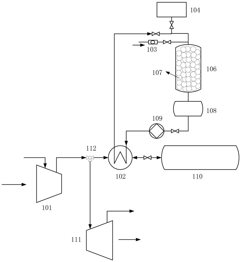
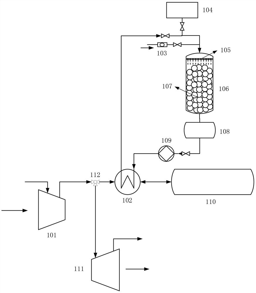
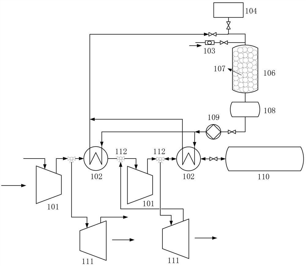
[0043] like Figure 1~Figure 6 Among them, a compressed air energy storage system based on a common circuit for heat storage and heat release is characterized in that it includes a compressor 101, a heat exchanger 102, a packed bed heat storage device 106, a liquid storage tank 108, a shielded pump 109, a high pressure The gas storage chamber 110 and the expander 111; the packed bed heat storage device 106, the liquid storage tank 108 and the shielded pump 109 are sequentially connected in series to form a heat storage and release circuit, and the heat exchanger 102 is located in the packed bed heat storage device 106 of the heat storage and release circuit In the heat storage and release circuit between the canned pump 109, the side of the heat exchanger 102 close to the packed bed heat storage device 106 is connected to the compressor 101, and the side of the heat exchanger 102 close to the canned pump 109 is connected to the high-pressure gas storage chamber 110, The expander...


PUM


Abstract

The invention provides a compressed air energy storage system and method based on a heat storage and release shared loop. A packed bed heat storage device, a liquid storage tank and a shielding pump are sequentially connected in series to form the heat storage and release loop; a heat exchanger is located in the portion, between the flow type packed bed heat storage device and the shielding pump, of the heat storage and release loop; the side, close to the flow type packed bed heat storage device, of the heat exchanger is connected with a compressor; the side, close to the shielding pump, of the heat exchanger is connected with a high-pressure air storage chamber; and an expansion machine is connected into a pipeline between the compressor and the heat exchanger. The problem that the input cost of the system is too high due to the fact that two loops in an original system complete heat storage and heat release is solved. The compressed air energy storage system has the advantages that the structure is simple, heat storage and heat release share one loop, the heat storage efficiency is high, the structure is compact, the number of needed auxiliary and component devices is reduced, and the cost is low.

Description

technical field [0001] The invention belongs to the technical field of energy storage, and relates to a compressed air energy storage system and method based on a common circuit for heat storage and heat release. Background technique [0002] Compressed air energy storage is a large-scale physical energy storage technology - using air as the energy storage medium, when the power consumption is low, the rich electricity can be converted into electrical energy in the form of high-pressure air through the conversion path of electrical energy-mechanical energy-molecular energy Large-scale physical storage converts the stored high-pressure air into electrical energy for external output through the conversion path of molecular internal energy-mechanical energy-electrical energy during peak electricity consumption. Compressed air energy storage technology has the advantages of environmental friendliness, long service life, large capacity and safe operation. [0003] Compressed air...

Claims


Application Information

Patent Timeline
Patent Type & Authority Applications(China)
IPC IPC(8): F04B41/02F04B39/16F01K27/00F01K13/00F28D20/00
CPCF04B41/02F04B39/16F01K27/00F01K13/00F28D20/00F28D20/0056Y02E60/14Y02E60/16
Inventor 谢宁宁孙长平尹立坤蔺新星张翼
Owner CHINA THREE GORGES CORPORATION
Why Eureka
Try Eureka