
Flue gas waste heat recycling device

A flue gas waste heat and waste heat technology, applied in the field of energy saving and emission reduction, can solve the problems of waste of resources, inability to respond, and a large amount of heat in the flue gas, and achieve the effect of improving combustion efficiency

Inactive Publication Date: 2021-06-25
马勇
View PDF0 Cites 1 Cited by
  • Summary
  • Abstract
  • Description
  • Claims
  • Application Information

AI Technical Summary

Problems solved by technology

[0003] The purpose of the present invention is to provide a flue gas waste heat recovery and utilization device to solve the problem that coal will inevitably produce sulfur dioxide during the combustion process proposed in the background technology. If it is discharged randomly, it will pollute the atmospheric environment. Most of the existing methods are The flue gas produced by coal combustion is desulfurized by spraying lime water through the desulfurization tower, and then discharged, but the flue gas after spraying still has a lot of heat, resulting in a waste of resources, which cannot respond to the national call for energy conservation and emission reduction.

Method used


Image

  • Flue gas waste heat recycling device
  • Flue gas waste heat recycling device
  • Flue gas waste heat recycling device

Examples


Embodiment Construction

[0015] The following will clearly and completely describe the technical solutions in the embodiments of the present invention with reference to the accompanying drawings in the embodiments of the present invention. Obviously, the described embodiments are only some, not all, embodiments of the present invention. Based on the embodiments of the present invention, all other embodiments obtained by persons of ordinary skill in the art without making creative efforts belong to the protection scope of the present invention.

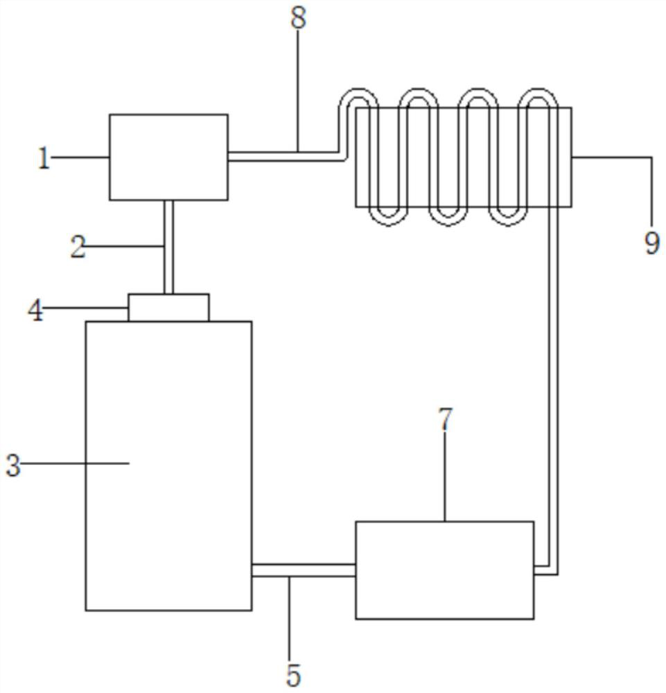
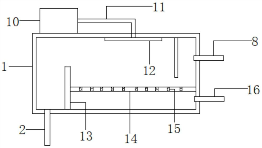
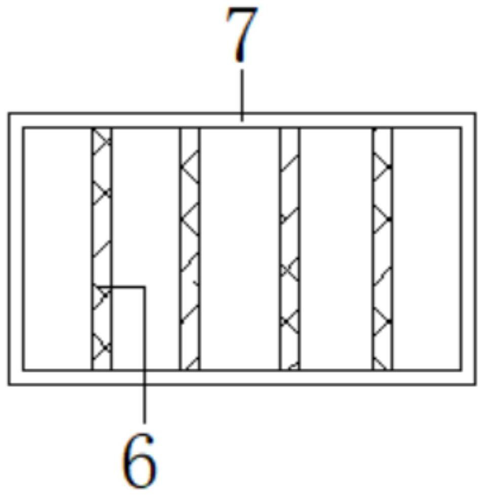
[0016] see Figure 1-3 , the present invention provides a technical solution: a flue gas waste heat recovery and utilization device, including a desulfurization recovery box 1, an atomized shower nozzle 12 is arranged on the top of the inner cavity of the desulfurized recovery box 1, and the water inlet on the top of the atomized shower nozzle 12 is connected to There is a spray pipe 11, and the other end of the spray pipe 11 is connected with an ammonia water...


PUM


Abstract

The invention belongs to the technical field of energy conservation and emission reduction, and particularly relates to a flue gas waste heat recycling device which comprises a desulfurization recycling box. An atomization shower nozzle is arranged on the top of an inner cavity of the desulfurization recycling box, and a water inlet in the top of the atomization shower nozzle is connected with a spraying pipe; the other end of the spraying pipe is connected with an ammonia water storage box; a first partition plate is vertically welded at the bottom of the inner cavity of the desulfurization recycling box, and a second partition plate is transversely arranged in the inner cavity of the desulfurization recycling box; the left side of the second partition plate is welded on the right side wall of the first partition plate, and the right side of the second partition plate is welded on the right side wall of the inner cavity of the desulfurization recycling box; through holes are evenly formed in a second partition plate body; and the right side of the desulfurization recycling box is connected with a first waste heat transport pipe and a recycling pipe. According to the flue gas waste heat recycling device, considerable by-products can be produced while desulfurization is conducted, and certain economic benefits are generated; and the combustion efficiency is greatly improved, and therefore the purposes of energy conservation and emission reduction are achieved.

Description

technical field [0001] The invention relates to the technical field of energy saving and emission reduction, in particular to a flue gas waste heat recovery and utilization device. Background technique [0002] Today, with increasingly strict requirements on the atmospheric environment, the awareness of environmental protection has been deeply rooted in people's minds. The flue gas purification and treatment of coal-fired boilers and industrial kilns is very important. The country's energy supply is still dominated by coal. Supplemented by other energy sources, from the perspective of economy and applicability, coal burning is currently the most economical industrial energy source. Others cannot be compared with coal, but coal will inevitably produce sulfur dioxide during the combustion process. If it is discharged randomly, it will pollute the atmosphere. Most of the existing methods are to desulfurize the flue gas produced by coal combustion through the desulfurization tow...

Claims


Application Information

Patent Timeline
IPC IPC(8): F23J15/02F23J15/04F23J15/06
CPCF23J15/025F23J15/04F23J15/06Y02E20/30
Inventor 马勇
Owner 马勇
Learn More