Check patentability & draft patents in minutes with Patsnap Eureka AI!

Drainage pipeline inflow and infiltration diagnosis method based on optical fiber distributed temperature measurement system

A technology for distributed optical fiber and drainage pipes, applied in thermometers, measuring heat, analyzing materials, etc., can solve problems such as blocking, emptying, dredging, pipelines that cannot be blocked and emptied, and difficult to implement CCTV detection, etc., to achieve Low cost, improving diagnostic efficiency and accuracy, and facilitating large-scale promotion and application

Active Publication Date: 2021-06-25
TONGJI UNIV
View PDF7 Cites 1 Cited by
  • Summary
  • Abstract
  • Description
  • Claims
  • Application Information

AI Technical Summary

Problems solved by technology

Pipeline CCTV imaging technology (Closed Circuit Television, CCTV) is currently the most commonly used technical method in drainage pipeline inspection, but pipeline CCTV inspection requires operations such as blocking, emptying, and dredging, and the inspection fee per kilometer of pipeline is 5-25 10,000 yuan, the average city can’t afford it
In addition, under the condition of high water level of the rainwater main pipe, it is difficult to implement CCTV detection because the pipe cannot be blocked and emptied

Method used


Image

  • Drainage pipeline inflow and infiltration diagnosis method based on optical fiber distributed temperature measurement system
  • Drainage pipeline inflow and infiltration diagnosis method based on optical fiber distributed temperature measurement system
  • Drainage pipeline inflow and infiltration diagnosis method based on optical fiber distributed temperature measurement system

Examples


Embodiment

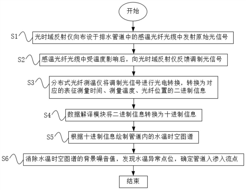
[0049] A method for diagnosing inflow and infiltration of drainage pipes based on an optical fiber distributed temperature measurement system. Using the water temperature difference between the external water and the water stored in the pipe, an optical cable is laid in the pipe to monitor the temperature abnormal points, and these temperature abnormal points are determined as mixed. The connection / damage point, the present invention provides an optical fiber distributed temperature measurement system, the optical fiber distributed temperature measurement system includes an optical time domain reflectometer, a data interpretation module, a temperature-sensing optical fiber cable and a distributed optical fiber thermometer, The field reflectometer includes an optical signal transmitting module and an optical signal receiving module. The optical signal transmitting module is used to generate the original optical signal and import it into the temperature-sensitive optical fiber cab...


PUM


Abstract

The invention relates to a drainage pipeline inflow and infiltration diagnosis method based on an optical fiber distributed temperature measurement system. The drainage pipeline inflow and infiltration diagnosis method comprises the following steps that S1, an optical time domain reflectometer transmits an original optical signal to a temperature sensing optical fiber cable arranged in a drainage pipeline; S2, after the temperature sensing optical fiber cable is influenced by the temperature, a modulation optical signal is fed back to the optical time domain reflectometer; S3, the distributed optical fiber thermodetector performs photoelectric conversion on the modulated optical signal, and converts the modulated optical signal into corresponding binary information representing measurement time, measurement temperature and optical fiber position; S4, the data interpretation module converts the binary information into decimal information; S5, a water temperature space-time atlas in the pipeline is drawn according to the decimal information; and S6, a background noise value of the water temperature space-time atlas is eliminated, a water temperature abnormal point is found, a pipeline infiltration flow point is determined, and an inflow and infiltration abnormal point of the drainage pipeline is obtained. Compared with the prior art, the method has the characteristics of high-water-level operation, high-frequency continuous monitoring, low cost and accurate positioning.

Description

technical field [0001] The invention relates to the field of inflow and infiltration diagnosis of drainage pipes, in particular to a method for diagnosing inflow and infiltration of drainage pipes based on an optical fiber distributed temperature measurement system. Background technique [0002] The drainage pipe network is the lifeline of the city and an indispensable infrastructure to prevent urban waterlogging and improve the quality of urban water environment. In recent years, with the rapid development of urbanization, the length of my country's drainage pipes has reached 600,000 kilometers; however, after the urban drainage system is completed, it faces the problem of mixed connection, damage, etc. caused by the decline in the collection efficiency of sewage pipes, which increases the number of sewage plants. operating energy consumption, causing overflow pollution of the drainage system and deterioration of river water quality. It is estimated that in areas with high ...

Claims


Application Information

Patent Timeline
IPC IPC(8): G01K11/32G01N15/08G01N13/04
CPCG01K11/32G01N15/08G01N13/04Y02A20/20F16L2101/30G01K13/026F16L55/28
Inventor 尹海龙徐祖信郭龙天解铭
Owner TONGJI UNIV
Features
  • R&D
  • Intellectual Property
  • Life Sciences
  • Materials
  • Tech Scout
  • Unparalleled Data Quality
  • Higher Quality Content
  • 60% Fewer Hallucinations
Learn More