Novel common-mode rejection balun structure for magnetic resonance radio frequency coil
A radio-frequency coil and common-mode suppression technology, applied in waveguide devices, electrical components, connecting devices, etc., can solve the problems of large size, restrictions on the softness of flexible coils, and inability to adapt to the development needs of high-density flexible radio-frequency coils. Easy adjustment, improved reliability and low cost
- Summary
- Abstract
- Description
- Claims
- Application Information
AI Technical Summary
Problems solved by technology
Method used
Image
Examples
Embodiment 1
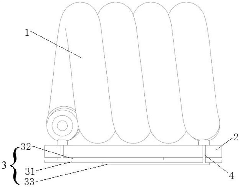
[0025] see figure 2 , a new type of common-mode suppression balun structure for 3T magnetic resonance radio frequency coils, consisting of upper, middle and lower three-layer structures, the upper layer is a solenoid 1 made of coaxial winding, and the middle layer is a hard printed circuit board 2, and the lower layer is a double-layer flexible printed circuit board 3.
[0026] The double-layer flexible printed circuit board 3 includes a substrate 31, an upper layer conductor 32 positioned on the upper surface of the substrate, and a lower layer conductor 33 positioned on the lower surface of the flexible substrate; the upper and lower layer conductors 32, 33 partially overlap, and the overlapping upper , The lower layer conductors 32, 33 together with the base material 31 in the middle form a planar flexible capacitor.
[0027] The axis of the solenoid 1 is parallel to the plane of the hard printed circuit board 2 , the outer insulating skin at both ends of the solenoid 1 i...
Embodiment 2
[0040] see Figure 4 , a new type of common mode suppression balun structure for 1.5T magnetic resonance radio frequency coil, which consists of upper, middle and lower three-layer structure, the upper layer is a solenoid 1 made of coaxial winding, and the middle layer is hard printed The circuit board 2, the lower layer is a double-layer flexible printed circuit board 3.
[0041] One difference from Embodiment 1 is the use of a rigid-flex printed circuit board, that is, the rigid printed circuit board 2 and the flexible printed circuit board 3 are directly integrated as a whole, so that the cost will be relatively high, but the penetrating rigid printed circuit board and the flexible printed circuit board can be used directly. The via hole 7 of the flexible printed circuit board is electrically connected, and it is no longer necessary to use thin copper wires to connect the two printed circuit boards, the process is relatively simple, and the reliability is also higher. The ...
PUM
 Abstract
Description
Claims
Application Information
 - R&D
- Intellectual Property
- Life Sciences
- Materials
- Tech Scout
- Unparalleled Data Quality
- Higher Quality Content
- 60% Fewer Hallucinations
Browse by: Latest US Patents, China's latest patents, Technical Efficacy Thesaurus, Application Domain, Technology Topic, Popular Technical Reports.
© 2025 PatSnap. All rights reserved.Legal|Privacy policy|Modern Slavery Act Transparency Statement|Sitemap|About US| Contact US: help@patsnap.com


