Detection control circuit and control method based on wireless charging

A detection control and circuit technology, applied in the direction of battery circuit devices, circuit devices, collectors, etc., can solve the problems of sensitive transmitting and receiving antennas, limited scope of application, high cost, etc., to reduce detection time, lower overall cost, and improve quality Effect

Pending Publication Date: 2021-06-25
SG MICRO
View PDF0 Cites 0 Cited by
  • Summary
  • Abstract
  • Description
  • Claims
  • Application Information

AI Technical Summary

Problems solved by technology

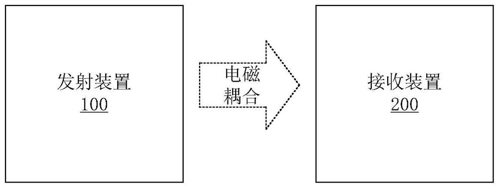
[0005] In the existing wireless charging scheme, the detection of the receiving device 200 is always on, so it will cause a lot of power consumption
At the same time, the existing wireless charging scheme must use a wireless charging chip with a protocol, as well as supporting receiving and transmitting antennas, according to the manufacturer's reference scheme, to detect whether the receiving module exists, the cost is high, and wireless charging in the process The equipment is sensitive to the transmitting and receiving antennas, and the scope of application is limited

Method used


Image

  • Detection control circuit and control method based on wireless charging
  • Detection control circuit and control method based on wireless charging
  • Detection control circuit and control method based on wireless charging

Examples


Embodiment Construction

[0038] In order to facilitate the understanding of the present invention, the present invention will be described more fully below with reference to the associated drawings. Preferred embodiments of the invention are shown in the accompanying drawings. However, the present invention can be implemented in different forms and is not limited to the embodiments described herein. On the contrary, these embodiments are provided to make the understanding of the disclosure of the present invention more thorough and comprehensive.

[0039] Unless otherwise defined, all technical and scientific terms used herein have the same meaning as commonly understood by one of ordinary skill in the technical field of the invention. The terms used herein in the description of the present invention are for the purpose of describing specific embodiments only, and are not intended to limit the present invention.

[0040] Hereinafter, the present invention will be described in detail with reference t...


PUM


Abstract

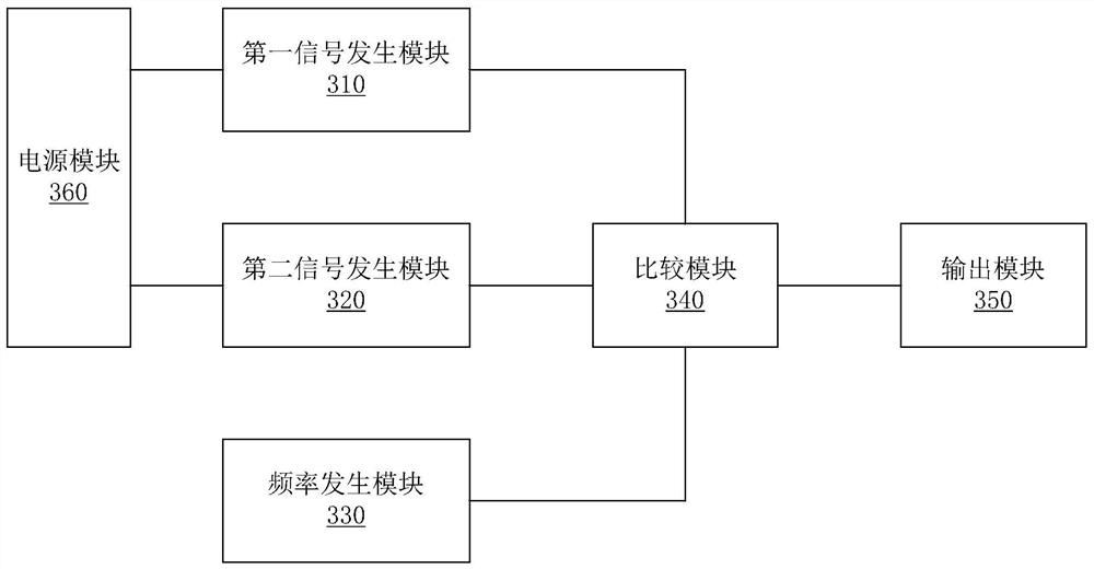
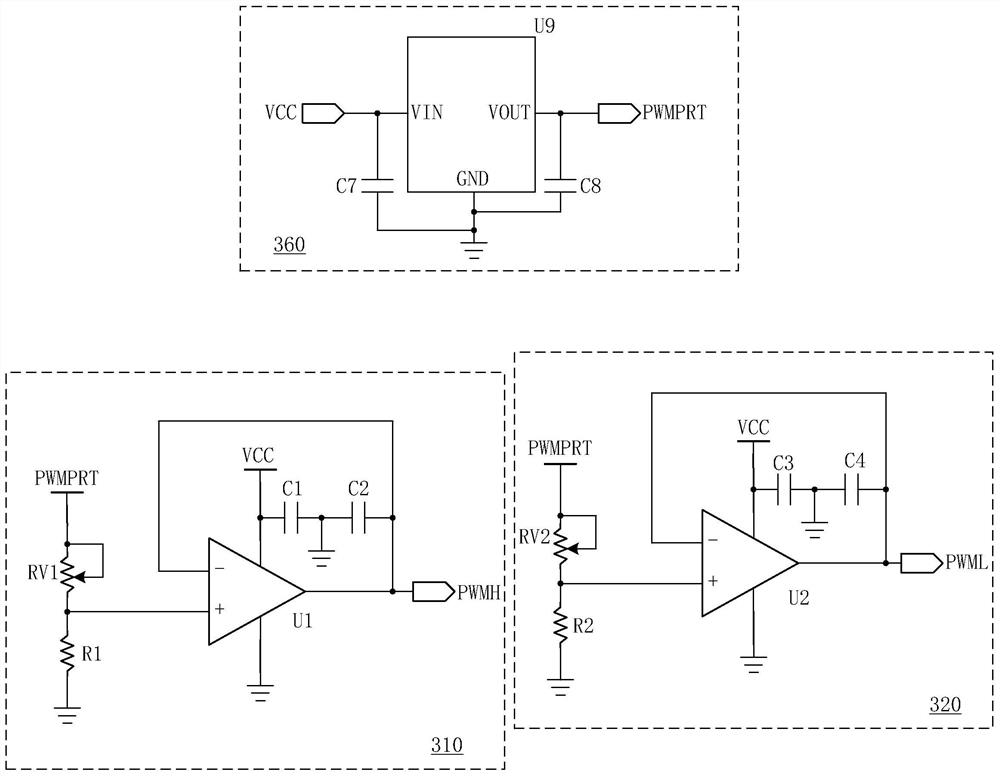
The invention discloses a detection control circuit and method based on wireless charging. The detection control circuit comprises: a power supply module used for outputting a second power supply voltage according to a first power supply voltage; a first signal generation module used for outputting a first threshold voltage with an adjustable voltage value according to the second power supply voltage; a second signal generation module used for outputting a second threshold voltage with an adjustable voltage value according to the second power supply voltage; a frequency generation module used for outputting a frequency-adjustable reference alternating current signal; a comparison module used for outputting a first pulse width modulation signal according to the first threshold voltage and the reference alternating current signal and outputting a second pulse width modulation signal according to the second threshold voltage and the reference alternating current signal; and an output module used for outputting an enabling control signal according to the first pulse width modulation signal and the second pulse width modulation signal. According to the invention, a communication protocol and a wireless charging chip do not need to be used, the cost is low, the effective duration of detection is adjustable, and the detection power consumption can be reduced.

Description

technical field [0001] The invention relates to the technical field of wireless charging, in particular to a detection control circuit and a control method based on wireless charging. Background technique [0002] With the development of electronic technology, electronic technology has developed from radar, satellite and communication applications to scientific research, medicine, biology and people's life and other aspects. At present, the application of electronic technology is closely related to our life, and the application and promotion of wireless charging has become a major trend in multimedia, household appliances, mobile phones, computers, etc. in our life. [0003] Wireless charging uses near-field induction, and the wireless charging transmitting device transmits energy to the receiving antenna or coil of the wireless charging receiving device through its transmitting antenna or coil, and the wireless charging receiving device uses the energy it receives to charge...

Claims


Application Information

Patent Timeline
IPC IPC(8): H02J7/00
Inventor 苏益
Owner SG MICRO
Why Eureka
Try Eureka