Direct reduction shaft furnace with probe for interior gas analysis
A gas analysis system and probe technology, used in the internal sensor of the direct reduction shaft furnace, the field of the direct reduction shaft furnace
Pending Publication Date: 2021-06-25
ARCELORMITTAL INVESTIGACION Y DESARROLLO SL
View PDF5 Cites 0 Cited by
- Summary
- Abstract
- Description
- Claims
- Application Information
AI Technical Summary
Problems solved by technology
Therefore, since there are currently no in situ measurements of gas analysis inside the shaft furnace, technicians can only model the DR reduction zone based on its inputs and outputs (gas and solids)
Method used
View moreImage
Smart ImageViewing Examples

Examples
Embodiment Construction
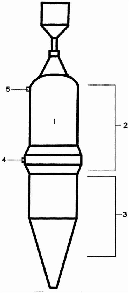
[0026] The invention relates to a DR shaft furnace with at least one probe arranged vertically in its reduction zone. The probes preferably extend from the top to the bottom of the reducing zone. The probe allows gas sampling along its length and delivery of the gas to at least one type of gas analysis device and pressure measurement instrumentation. The probe may also allow the temperature of the gas sample to be measured as the gas sample is taken. Thus, the DR furnace and probe combination of the present invention allows gas samples and temperatures to be taken at different levels inside the furnace. Probes may be mounted vertically along the diameter of the DR shaft at one or more locations.
Login to View More PUM
 Abstract
A direct reduction shaft furnace having at least one probe disposed vertically within the reduction zone thereof. The probe preferably extends from the top to the bottom of the reduction zone. The probe allows for gas sampling along the length thereof and transmittal of the gas to at least one type of gas analysis device. The probe may also allow for the measurement of the temperature and pressure of the gas sample as it is taken.
Description
technical field [0001] The invention generally relates to any type of shaft furnace including direct reduction shaft furnaces. More specifically, the present invention relates to internal sensors for direct reduction shaft furnaces. In particular, the invention relates to a direct reduction shaft furnace having at least one probe to measure temperature and collect gas samples at different levels within its reduction zone. Background technique [0002] The direct reduction method used to produce high-quality metallized pellets has an extremely high degree of thermal efficiency. Direct reduced iron (DRI) is produced by the direct reduction of iron ore (in the form of lumps, pellets or fines) to iron by means of reducing gases. Hematite / magnetite is suitable for direct reduction. [0003] Reduced iron gets its name from the chemical changes that iron ore undergoes when it is heated in a furnace at high temperatures in the presence of hydrocarbon-rich gases, carbon monoxide, ...
Claims
Login to View More Application Information
Patent Timeline
 Patent Type & Authority Applications(China)
IPC IPC(8): C21B7/24F27D21/00F27D19/00F27B1/26F27B1/28H01J49/04
CPCF27B1/26F27B1/28F27D19/00F27D21/00F27D21/0014H01J49/0422C21B7/24Y02P10/143G01K13/024C21B13/02F27D2021/0007
Inventor 迈赫迪·法拉哈尼贾斯廷·法利乔治·茨维克加布里埃尔·耶苏·卢塞纳莫戈利翁
Owner ARCELORMITTAL INVESTIGACION Y DESARROLLO SL