Low-temperature heat recovery system

A technology of low-temperature heat recovery and water heat exchanger, which is applied in heat pumps, lighting and heating equipment, and compressors with reversible cycles, etc. It can solve problems such as endangering the safety of the unit, increasing the specific volume of the refrigerant, and limiting climate and environmental conditions. , to achieve the effect of improving system capacity and energy efficiency, increasing the subcooling degree of the main road, and expanding the operating range

Pending Publication Date: 2021-06-29
ZHEJIANG ZHONGGUANG ELECTRIC CO LTD
View PDF0 Cites 0 Cited by
  • Summary
  • Abstract
  • Description
  • Claims
  • Application Information

AI Technical Summary

Problems solved by technology

[0004] However, limited by the climate and environmental conditions, ordinary heat recovery air-cooled heat pump units can only operate at an ambient temperature above -15°C
For severe cold regions, due to the low temperature, the specific volume of the refrigerant will increase, which will lead to insufficient suction mass flow rate of the compressor, insufficient cooling of the motor, and high discharge temperature, which will endanger the safety of the unit and fail to operate normally.
The condensing temperature is related to the water temperature. For heating or hot water working conditions, the water temperature remains unchanged, the condensing temperature basically remains unchanged, and the evaporating temperature decreases due to the decrease of the ambient temperature. The lower the ambient temperature, the greater the compression ratio of the compressor, and the discharge temperature Higher, the unit cannot operate safely

Method used


Image

  • Low-temperature heat recovery system
  • Low-temperature heat recovery system
  • Low-temperature heat recovery system

Examples


Embodiment Construction

[0027] Embodiments of the present invention are described in detail below, and examples of the embodiments are illustrated in the drawings in which the same or similar components are denoted by the same or similar components or elements having the same or similar functions. The embodiments described below are illustrative of the embodiments described below, intended to be used to explain the utility model, without understanding the limitation of the invention.

[0028] In the description of the present invention, it is to be understood that the terms "center", "longitudinal", "horizontal", "length", "width", "thickness", "upper", "under", "front", "Post", "left", "right", "vertical", "horizontal", "top", "bottom", "clockwise", "counterclock", "counterclock", "counterclockwise", based on orientation or positional relationship The orientation or positional relationship shown in the drawings is intended to facilitate the description of the utility model and simplified description, ra...


PUM


Abstract

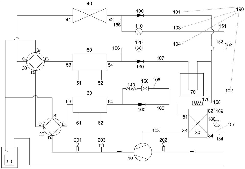
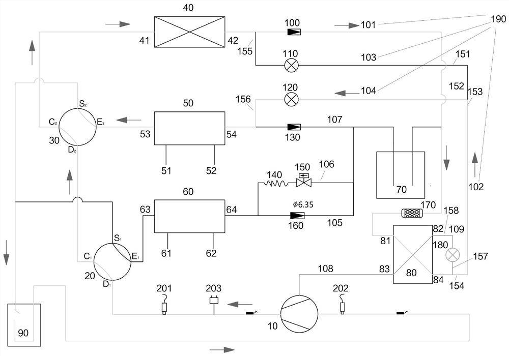
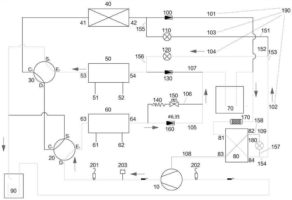
The invention relates to the technical field of heat pump systems, in particular to a low-temperature heat recovery system. The low-temperature heat recovery system involves a compressor, a first four-way valve, a second four-way valve, an air side heat exchanger, an air conditioner water heat exchanger, a hot water heat exchanger, a liquid storage device, an economizer, a first throttling element, a second throttling element and a main flow pipeline, and the low-temperature heat recovery system comprises a refrigeration cycle mode, a heating cycle mode, a hot water cycle mode and a heat recovery cycle mode. According to the technical scheme, the four modes are supercooled through the economizer, on one hand, the exhaust temperature can be reduced, and the operation range is expanded; on the other hand, the supercooling degree of a main circuit is increased, therefore the system can normally operate in a low-temperature environment, and the system capacity and energy efficiency are improved; and only one liquid storage device is arranged, and a refrigerant does not pass through the liquid storage device in the refrigeration cycle mode, so that the supercooling degree loss of the system is favorably reduced, and meanwhile, the refrigerant injection amount is also reduced.

Description

Technical field [0001] The utility model relates to the technical field of heat pump systems, and more particularly to a low temperature heat recovery system. Background technique [0002] The heat pump is a highly efficient energy saving device that takes full advantage of low-grade thermal energy. The heat can be passed from the high temperature object to the low temperature object, but cannot be carried out in the opposite direction. The working principle of the heat pump is to force heat from the low temperature material to the mechanical device from the low temperature material to the high temperature object. It can also obtain a large amount of supply, which can effectively use the low product position that is difficult to apply. Thermal can use it to achieve energy saving purposes. [0003] Air conditioning heat pump technology uses the application of air conditioning and heating and hot water, which greatly enhances human life quality. For air conditioning and heating, th...

Claims


Application Information

Patent Timeline
Patent Type & Authority Applications(China)
IPC IPC(8): F25B13/00F25B30/06F25B39/00F25B41/20F25B41/385F25B43/00F25B49/02
CPCF25B13/00F25B30/06F25B39/00F25B43/006F25B49/02
Inventor 王鹏周锦杨袁晓军王磊
Owner ZHEJIANG ZHONGGUANG ELECTRIC CO LTD
Why Eureka
Try Eureka