
Composite submarine cable protection system convenient to detect, position and repair

A protection system and submarine cable technology, applied in the direction of insulated cables, cables, circuits, etc., can solve the problems of inconvenient regular detection of cable surface and cable internal structure, interruption of signal information transmission, inconvenience of cables being bitten by fish, etc., to achieve relief Loss of cost, possibility of reduction, effect of low cost

Inactive Publication Date: 2021-06-29
盐城市孔瑾商贸有限公司
View PDF0 Cites 1 Cited by
  • Summary
  • Abstract
  • Description
  • Claims
  • Application Information

AI Technical Summary

Problems solved by technology

[0003] 1. The traditional cables are laid on the seabed or shoal with bare leaks. Due to the erosion of seawater, the cables are easily eroded, resulting in the interruption of signal information transmission;
[0004] 2. Traditional cables are not convenient to regularly detect the surface of the cable and the internal structure of the cable, which makes it risky for the staff to enter the seabed for inspection and increases the difficulty of work;
[0005] 3. Traditional cables are not easy to detect the protective shell in the deep sea. Seawater erosion will easily corrode the protective cable shell, causing the cable to be eroded by seawater again, and the inside of the machine will also be damaged;
[0006] 4. Traditional cables are inconvenient to obtain results after self-inspection and transmit information to inform the location, and it is not convenient to avoid cables being bitten by fish

Method used


Image

  • Composite submarine cable protection system convenient to detect, position and repair
  • Composite submarine cable protection system convenient to detect, position and repair
  • Composite submarine cable protection system convenient to detect, position and repair

Examples


Embodiment Construction

[0026] In the description of the present invention, it should be noted that the orientations or positional relationships indicated by the terms "upper", "lower", "inner", "outer", "top / bottom" etc. are based on the orientations shown in the drawings Or positional relationship is only for the convenience of describing the present invention and simplifying the description, but does not indicate or imply that the device or element referred to must have a specific orientation, be constructed and operated in a specific orientation, and therefore should not be construed as limiting the present invention. In addition, the terms "first" and "second" are used for descriptive purposes only, and should not be understood as indicating or implying relative importance.

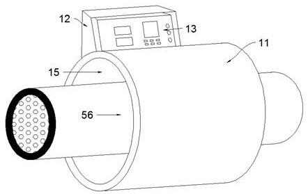
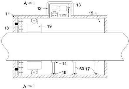
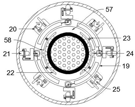
[0027] refer to Figure 1-6 , according to an embodiment of the present invention, a composite submarine cable protection system that is convenient for detection, positioning and repair, includes a cylindrical cover 11, and...


PUM


Abstract

The present invention discloses a composite submarine cable protection system convenient to detect, position and repair. The system comprises a cylindrical cover body, the cover body is internally provided with a cylindrical detection cavity of which the annular side wall is a mirror surface, the left side wall in the detection cavity is provided with a wireless charger, and the bottom wall of the detection cavity is fixedly provided with a plurality of fixing blocks which are transversely arranged. The upper side of the fixing block is connected with a supporting rod through a coil spring, a bearing block is fixedly arranged on the upper side of the supporting rod, a cable penetrating through the left end and the right end of the cover body is borne on the upper side of the supporting rod, a device body is arranged in the detection cavity, a penetrating groove penetrating left and right is formed in the device body, and the cable penetrates through the penetrating groove; and by wrapping the cable for protection, the possibility of being bitten by fishes is avoided, the possibility of cable damage is reduced, the maintenance cost of the protection shell is low, accurate positioning can be achieved after detection, and maintenance is simple.

Description

technical field [0001] The invention relates to the field of composite submarine cable technology, in particular to a composite submarine cable protection system that is convenient for detection, positioning and repair. Background technique [0002] Submarine cables are cables wrapped in insulating material and laid on the seabed for telecommunications transmission. Submarine cables are divided into submarine communication cables and submarine power cables. Modern submarine cables use optical fibers as materials to transmit telephone and Internet signals. Submarine cables are divided into submarine communication cables and submarine power cables. Submarine communication cables are mainly used for communication services, which are expensive, but have a high degree of confidentiality. Submarine power cables are mainly used to transmit high-power electric energy underwater, and have the same function as underground power cables, but the application occasions and laying method...

Claims


Application Information

Patent Timeline
IPC IPC(8): H01B7/17H01B7/28H01B7/32H01B7/40
CPCH01B7/17H01B7/2806H01B7/32H01B7/328H01B7/40
Inventor 彭红兰
Owner 盐城市孔瑾商贸有限公司
Learn More