
Dewatering well structure in foundation pit and construction method

A construction method and technology of dewatering wells, which are applied in infrastructure engineering, construction, etc., can solve the problems of high construction cost and construction, and achieve the effects of reducing construction workload, ensuring construction quality, and saving construction costs

Pending Publication Date: 2021-07-02
THE NO 6 ENG CO LTD OF CHINA RAILWAY 20TH BUREAU GRP
View PDF6 Cites 1 Cited by
  • Summary
  • Abstract
  • Description
  • Claims
  • Application Information

AI Technical Summary

Problems solved by technology

[0003] The main purpose of the present invention is to propose a structure and construction method of the dewatering well in the foundation pit, aiming at solving the problems of high construction cost and construction of the dewatering well in the foundation pit in the prior art

Method used


Image

  • Dewatering well structure in foundation pit and construction method
  • Dewatering well structure in foundation pit and construction method
  • Dewatering well structure in foundation pit and construction method

Examples


no. 6 example

[0077] Based on the above embodiment, it is the sixth embodiment of the present invention, step S502 includes:

[0078] Step S5021, measuring the staked out side wall edge;

[0079] Step S5022, inserting double rows of reinforcement bars at the sideline, with an insertion depth of 0.3m-0.5m;

[0080] Step S5023, erecting the formwork of the side wall, and performing side wall pouring construction, the thickness of the side wall 2 is not less than 300mm.

[0081] Such as Figure 4 As shown, in this embodiment, the surveyor sets out the side wall 2, and inserts vertical double rows of Φ12 wall reinforcement bars 22 according to the outer edge of the side wall 2, and the wall reinforcement bars 22 have a depth of 300mm into the soil. The double row of reinforcing bars 22 further improves the strength of the side wall 2 , avoids deformation and damage of the side wall 2 caused by excessive water pressure, and further improves the construction quality of the foundation pit 100 . ...

no. 8 example

[0085] Based on the above embodiment, it is the eighth embodiment of the present invention, step S503 includes:

[0086] Step S5031, using medium sand to backfill the dewatering well to 500mm below the wellhead of the dewatering well;

[0087] Step S5032, leveling the backfill soil in the dewatering well, and pouring C35P8 micro-expansion concrete into the dewatering well to seal off the dewatering well.

[0088] In this implementation, after the concrete pouring of the side wall 2 is completed, the formwork is removed and the well is backfilled to seal the well. The backfill material of the dewatering well 1 is medium sand. The surface level is equal to the top of the cushion layer.

[0089] Based on the foregoing embodiments, step S300 includes:

[0090] Step S310, installing the water pump and its supporting circuit control facilities;

[0091] Step S320, seal the dewatering well with a cover plate, and make a protective fence around the wellhead;

[0092] Step S330, co...


PUM

PropertyMeasurementUnit
Thicknessaaaaaaaaaa

Abstract

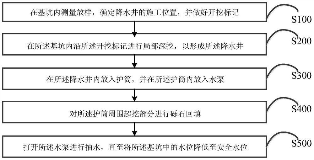
The invention discloses a dewatering well structure in a foundation pit and a construction method. The method comprises the steps that the construction position of a dewatering well is determined through survey and setting-out in the foundation pit, and an excavation mark is made; local deep excavation is conducted in the foundation pit along the excavation mark, so that the dewatering well is formed; a protective barrel is placed in the dewatering well, and a water pump is placed in the protective barrel; gravel backfilling is conducted on the over-excavation part around the protective barrel; and the water pump is started to pump water till the water level in the foundation pit is lowered to the safe water level. According to the dewatering well structure in the foundation pit and the construction method, the construction workload of the dewatering well is greatly reduced, and the construction cost is reduced; and through cooperation of a submersible pump and the protective barrel, the effective dewatering range is reasonably enlarged, the dewatering effect is guaranteed, and the construction quality is guaranteed while the construction cost is reduced.

Description

technical field [0001] The invention relates to the technical field of building construction, in particular to a structure of a dewatering well in a foundation pit and a construction method. Background technique [0002] With the development of urban underground space, more and more large-scale deep foundation pits are being constructed, and the control of groundwater during construction is becoming more and more important. The shear strength and the stability of the foundation pit are convenient for earthwork excavation and construction in the foundation pit. The general dewatering measures reduce the groundwater level. For large foundation pits, due to the large area of ​​the foundation pit, if the large-scale excavation of the dewatering well dewaters the construction area will be too large, which will increase the The construction cost of the dewatering well, and the use of light well point dewatering is difficult to achieve the effect required by the construction, resul...

Claims


Application Information

Patent Timeline
IPC IPC(8): E02D19/10E02D19/06
CPCE02D19/10E02D19/06
Inventor 张烈霞陶睿刘德兵吴红兵段锋吕超高旗郭毅喻敬贤张峰刘奎王龙靖
Owner THE NO 6 ENG CO LTD OF CHINA RAILWAY 20TH BUREAU GRP
Learn More