
Compact anti-blocking radioactive flue gas cooling device

A flue gas cooling device and anti-clogging technology, which is applied in the direction of climate change adaptation, climate sustainability, lighting and heating equipment, etc., can solve the problem of not meeting the requirements of compact integrated design, difficult cleaning and maintenance of cooling equipment, and lack of Particle separation and other issues, to achieve efficient cooling and preliminary purification, compact structure, and minimized equipment volume

Pending Publication Date: 2021-07-02
CHINA INST FOR RADIATION PROTECTION
View PDF5 Cites 0 Cited by
  • Summary
  • Abstract
  • Description
  • Claims
  • Application Information

AI Technical Summary

Problems solved by technology

For conventional flue gas cooling equipment, especially the tube-and-tube heat exchanger, the inner tube is relatively thin, and it is easy to be blocked by dust and other particles in the flue gas during long-term operation. It is not easy to clean and maintain the blocked cooling equipment; at the same time, the conventional flue gas cooling device does not have the function of preliminary separation of particles in the flue gas, and it is necessary to add particle separation equipment in the subsequent process, which cannot meet the needs of compact integration. Design requirements

Method used


Image

  • Compact anti-blocking radioactive flue gas cooling device
  • Compact anti-blocking radioactive flue gas cooling device

Examples


Embodiment Construction

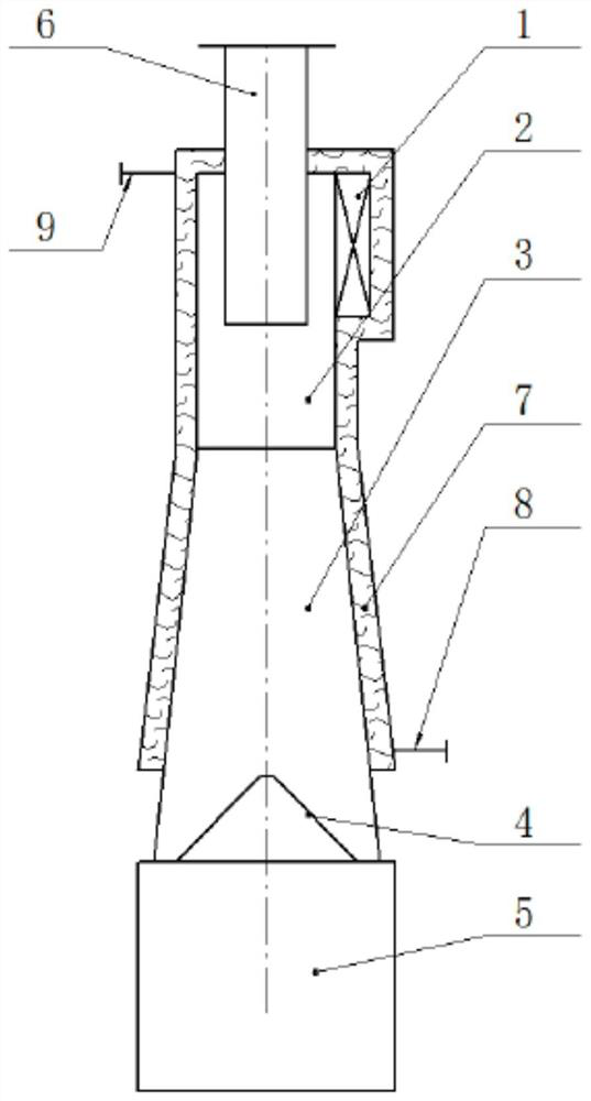
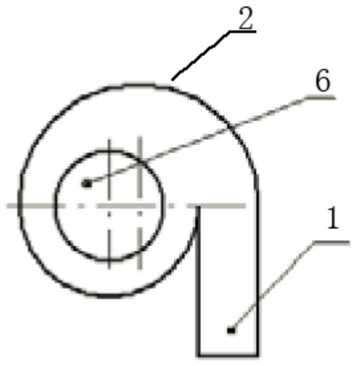
[0017] Such as figure 1 , figure 2 As shown, a compact anti-blocking radioactive fume cooling device includes an inner shell, an ash hopper 5 installed at the bottom of the inner shell, an air intake pipe 1 arranged on the top of the inner shell and communicated with the inner shell, and an air intake pipe 1 is connected tangentially to the cylinder 2, and the flue gas enters the cylinder 2 tangentially through the intake pipe 1. The inner shell includes the cylinder 2 and the cone 3 connected to the cylinder 2. The cylinder 2 and the cone 3 are integrated. Forming, the cone 3 is in the shape of an inverted cone, the bottom of the cone 3 is provided with a reflective screen 4, the top of the reflective screen 4 is provided with air holes, and there is an annular gap between the reflective screen 4 and the inner wall of the cone 3, the cone 3 The inner cavity of the ash hopper communicates with the inner cavity of the ash hopper 5 through the vent holes on the reflective scre...


PUM


Abstract

The invention relates to a compact anti-blocking radioactive flue gas cooling device. The compact anti-blocking radioactive flue gas cooling device comprises an inner shell, an ash bucket installed at the bottom of the inner shell and a gas admission pipe arranged at the top of the inner shell and communicated with the inner shell, the inner shell comprises a barrel and a cone connected with the barrel, a reflecting screen is arranged at the bottom of the cone, vent holes are formed in the top of the reflecting screen, an annular gap is formed between the reflecting screen and the inner wall of the cone, and an inner cavity of the cone is communicated with an inner cavity of the ash bucket through the vent holes in the reflecting screen and the annular gap; and a water cooling jacket is arranged at the outer side of the inner shell and wraps the outer side of the barrel and the outer side of the cone, and the two ends of the water cooling jacket are connected with a cooling water filling pipe and a cooling water discharging pipe respectively. When the compact anti-blocking radioactive flue gas cooling device is used, high-temperature flue gas moves along the inner shell of the device and is in contact with the water cooling wall, so that a cooling effect is achieved; and meanwhile, high-temperature dust-containing flue gas tangentially enters the compact anti-blocking radioactive flue gas cooling device, and particulate matters in the flue gas can be preliminarily captured and dedusted under the action of centrifugal force.

Description

technical field [0001] The invention relates to the field of cooling and purifying radioactive high-temperature flue gas, in particular to a compact anti-blocking radioactive flue gas cooling device. Background technique [0002] Nuclear facilities such as military industry, scientific research, experiments, and nuclear power plants will generate a large amount of radioactive waste during operation and maintenance, of which combustible waste accounts for a large proportion (about 50%), such as plastics, rubber, cotton fabrics, wood, resin, waste oil, etc. , the average specific activity of most solid combustible wastes is ≤1×10 5 Bq / kg range. As one of the earliest radioactive waste volume reduction technologies, incineration is very suitable for the treatment of these low-level radioactive solid wastes. It can not only achieve a large volume reduction (volume reduction ratio can reach 80-120), but also realize the inorganicization of waste , which facilitates final dispos...

Claims


Application Information

Patent Timeline
Patent Type & Authority Applications(China)
IPC IPC(8): F23J15/06F23J15/02B01D45/16
CPCF23J15/06F23J15/025B01D45/16Y02A50/2351
Inventor 褚浩然张禹徐卫郑博文李晓海张晓斌杨利国李串莲贾成明杨丽莉阮佳晟崔晗王鹏陈睿胡磊
Owner CHINA INST FOR RADIATION PROTECTION
Learn More