Eddy current self-heating nitrogen replacement and detoxification device for dioxin-containing fly ash
A nitrogen replacement and self-heating technology, which is applied in waste heat treatment, heating room maintenance, lighting and heating equipment, etc., can solve the problems of high pollution products, instability, etc., and achieve the effect of improving completeness and energy saving effect
- Summary
- Abstract
- Description
- Claims
- Application Information
AI Technical Summary
Problems solved by technology
Method used
Image

Examples
Embodiment Construction
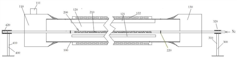
[0028] like Figure 1-4 The shown vortex self-heating nitrogen replacement and detoxification device containing dioxin-containing dust removal ash includes a rotatable kiln body 100. The vortex self-heating rotary kiln is selected, and the temperature rises rapidly, avoiding the start-up and shutdown time of traditional fuel kilns. Long, the disadvantages of high energy consumption.
[0029] The kiln body 100 is a hollow structure, with a preheating section 110 , a heating section 120 and a cooling section 130 arranged in a three-stage structure inside; the heating section 120 is wrapped with an induction heating device 122 .
[0030] The inductive heating device 122 has flexible and precise temperature control, good displacement reaction effect, high dioxin removal efficiency, and safer products.
[0031] Using electricity as the heat source, there is no need to supplement oxygen in the kiln to support fuel combustion, and the kiln is a reducing atmosphere, which is conduciv...
PUM
 Abstract
Description
Claims
Application Information