
A laboratory material automatic analysis system

An automatic analysis system and laboratory technology, applied in the field of material composition analysis, can solve problems such as cumbersome work, inability to install multiple robots, and high intensity, and achieve the effect of reducing interference, personnel settings and labor intensity.

Active Publication Date: 2022-03-22
SAIMO ELECTRIC
View PDF6 Cites 0 Cited by
  • Summary
  • Abstract
  • Description
  • Claims
  • Application Information

AI Technical Summary

Problems solved by technology

[0003] After the material sample is sent to the laboratory, it needs to go through a series of processing procedures such as material information identification, mixing, opening the sample bottle, micro-weighing and putting it into the corresponding container, and putting the weighed sample and the container into the corresponding instrument one by one to meet the test requirements. At present, these tasks in the laboratory are usually done manually by experimental operators. Not only is the work cumbersome and intensive, but there are also human factors such as fatigue and emotions, which can easily cause deviations and affect the test results of materials.
[0004] In recent years, with the rapid development of robot technology and the expansion of its application fields, the automation mode of laboratory material analysis robots has also emerged. However, for the application of industrial robots, most of them are positioned and installed at present, and can only be used within a certain working radius area. To complete the work, but there are many analytical instruments in the laboratory, and different laboratory instruments are usually arranged in different rooms, with large layout differences. Different instrument stations require multiple robots to work together. For places where robots are not used frequently, The use of multiple robots increases the overall cost, and even multiple robots cannot be installed in special venues

Method used


Image

  • A laboratory material automatic analysis system
  • A laboratory material automatic analysis system
  • A laboratory material automatic analysis system

Examples


Embodiment Construction

[0060] The present invention will be further described below in conjunction with the accompanying drawings.

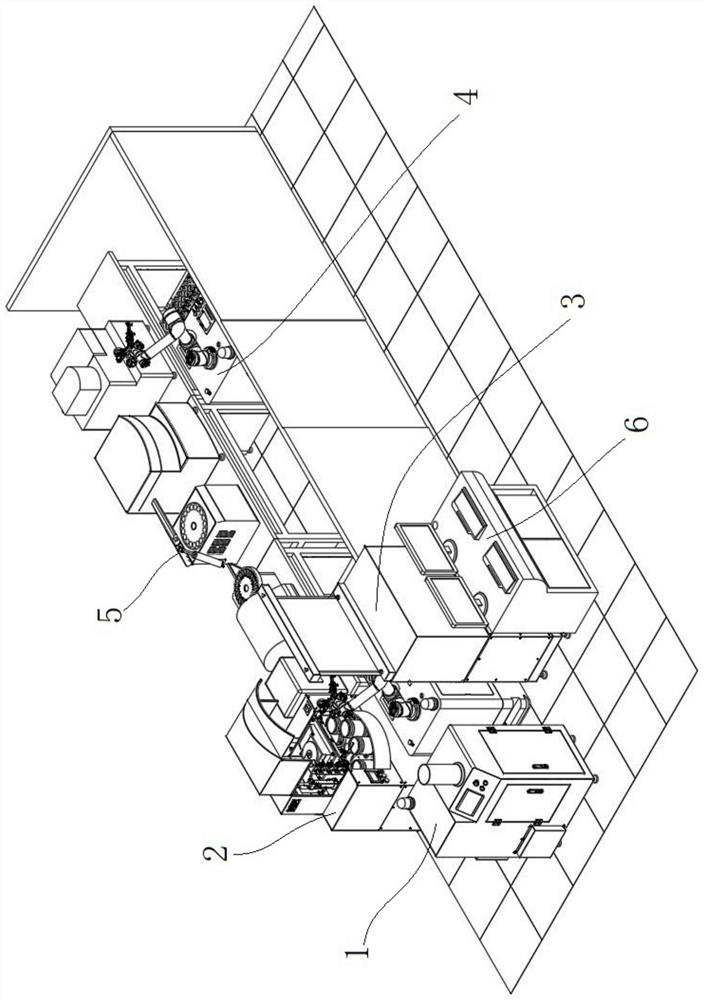
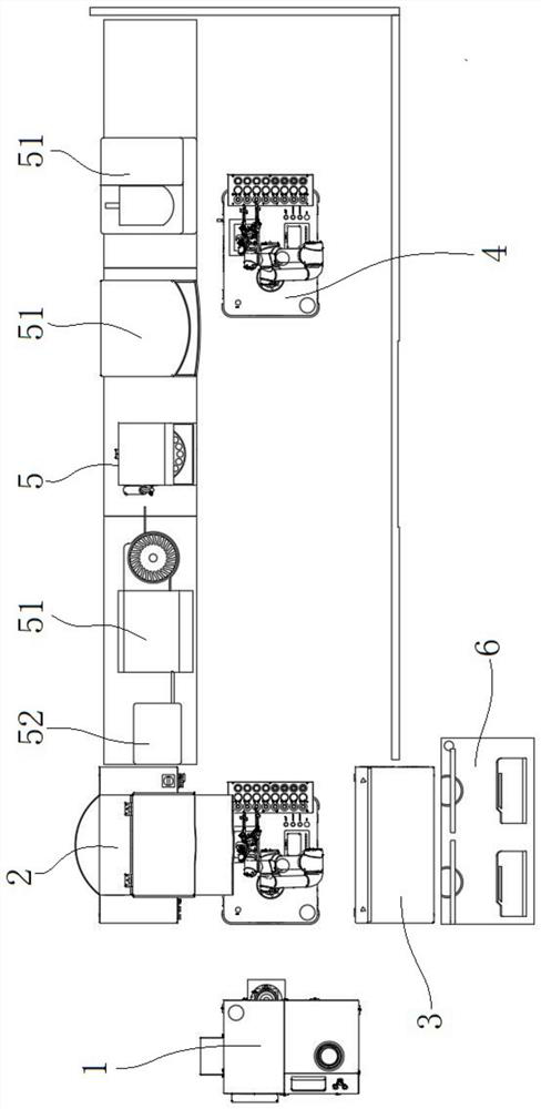
[0061] like figure 1 , figure 2 As shown, the laboratory material automatic analysis system includes the material sample barrel automatic receiving and opening output unit 1, the material accurate weighing unit 2, the crucible bench unit 3, the grabbing robot unit 4, the material analysis unit 5 and the centralized electric control unit Unit 6.

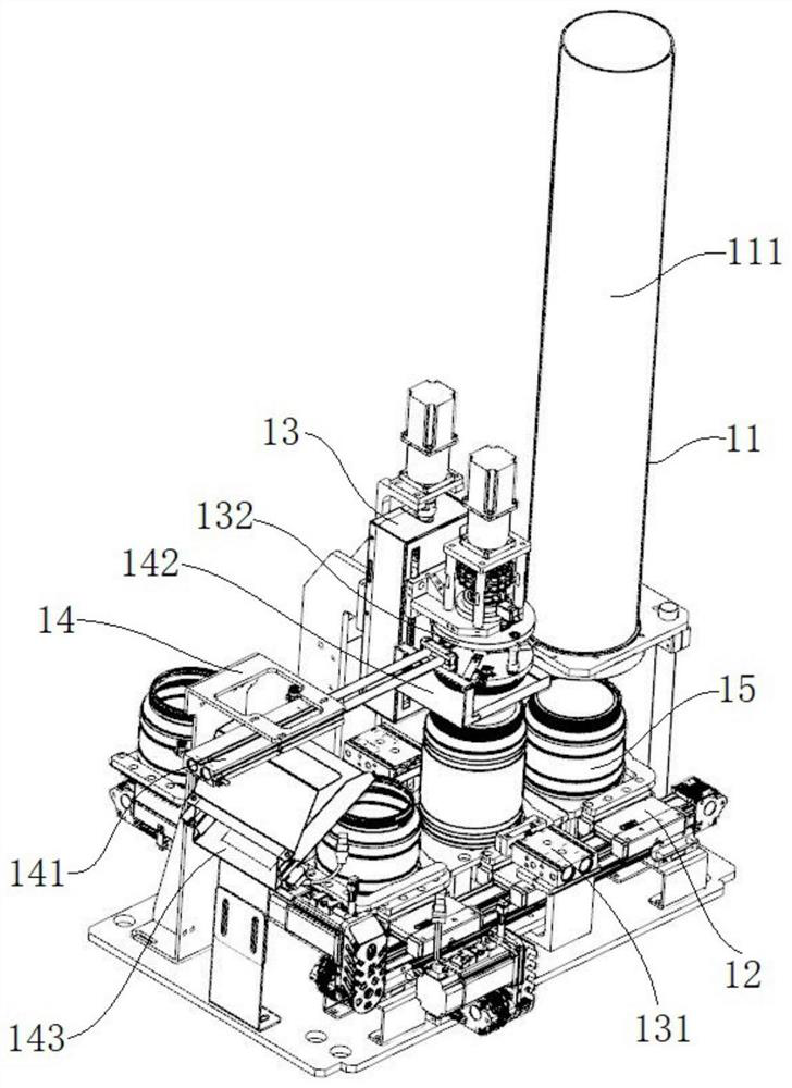
[0062] The automatic receiving and uncapping output unit 1 of the material sample bucket is used for automatically receiving and uncapping the material sample bucket 15 covered with a bung, and then positioning and outputting the material sample bucket 15 after uncapping, such as image 3 As shown, the material sample barrel automatic receiving and opening output unit 1 includes a sample barrel automatic receiving device 11 installed on the frame I, a sample barrel translational conveying device 12, a sample barrel clamping...


PUM


Abstract

The invention discloses a laboratory material automatic analysis system, which comprises a material sample barrel automatic receiving and opening output unit, a material accurate weighing unit, a crucible bench unit, a grabbing and stacking robot unit, a material analysis unit and a centralized electric control unit. The present invention is an intelligent digital control system, through the coordinated operation of each unit, it can automatically receive and output the material sample barrel with a lid, and quantitatively and accurately scoop the material sample in the opened material sample barrel to A series of automatic operations, such as accurate weighing in the crucible, automatic industrial analyzers for different types of automatic experimental analysis of material samples, and automatic storage and output of experimental results, can achieve improvement on the premise of reducing the personnel settings and labor intensity of experimental operators. The experimental efficiency of the material composition analysis experiment and the accuracy of the experimental data can greatly reduce the interference of human factors on the experimental process, and it is especially suitable for the laboratory material composition analysis.

Description

technical field [0001] The invention relates to an automatic laboratory material analysis system, in particular to an automatic analysis system suitable for automatic component analysis of materials such as crushed coal samples and ore samples, belonging to the technical field of material component analysis. Background technique [0002] Material composition analysis is a testing technique that uses analytical chemistry methods or analytical instruments to measure the chemical composition of materials. Taking the analysis of ore composition as an example, the composition of ores and mineral processing products refers to the useful, temporarily useless or unrecoverable and harmful elements or compounds contained in these materials and their content. The results of ore composition analysis are used to evaluate mineral processing tests. The most basic data such as the production technology level of the mineral processing plant and the technical and economic indicators of the mi...

Claims


Application Information

Patent Timeline
Patent Type & Authority Patents(China)
IPC IPC(8): G01N35/00
CPCG01N35/00584G01N35/0099
Inventor 厉达张开生刘振中孙宜敬李明辉
Owner SAIMO ELECTRIC
Learn More