A tensile high-strength hook forging forging device
A high-strength, hook-head technology, applied in forging/pressing/hammer devices, forging presses, forging presses, etc., can solve the problem of reducing the service life of the hook, increasing the shear force of the hook head and the structure, manual turning and positioning The progress is uncontrollable and other problems, to achieve the effect of improving the clamping accuracy, facilitating mass production, and facilitating installation and removal
- Summary
- Abstract
- Description
- Claims
- Application Information
AI Technical Summary
Problems solved by technology
Method used
Image
Examples
Embodiment 1
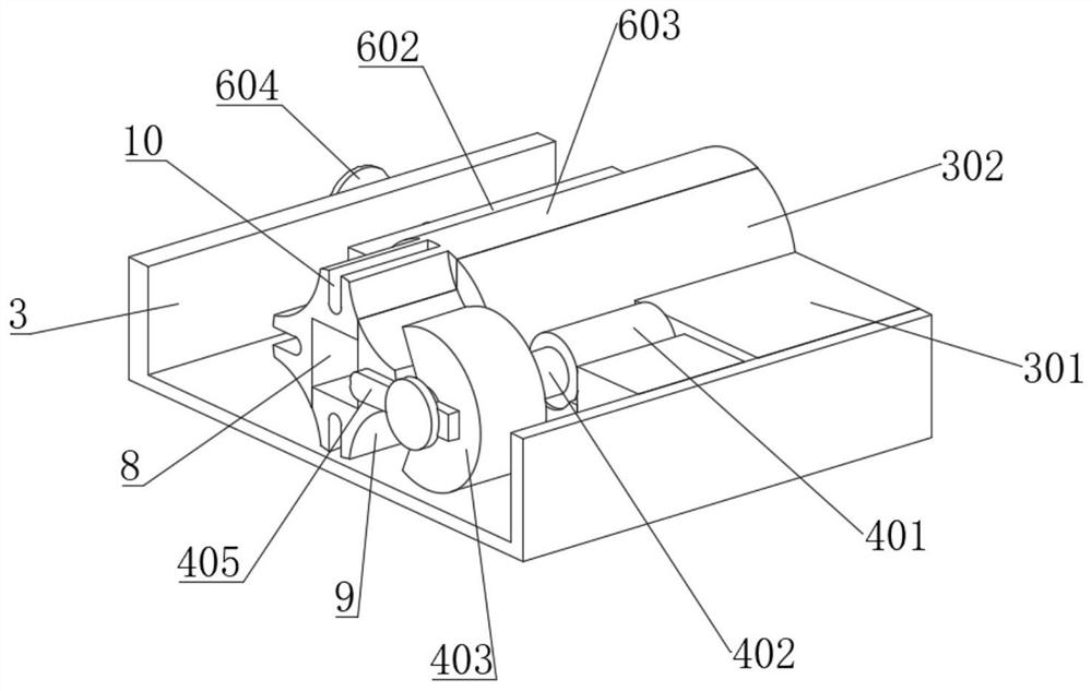
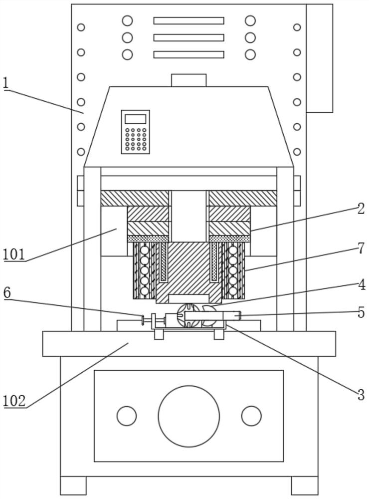
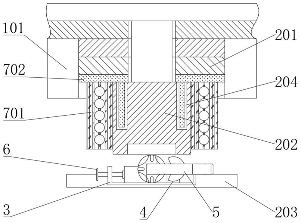
[0058] see Figure 1-13 , a forging device for tensile high strength hook head forgings, comprising a forging body 1, the upper end of the forging body 1 is fixedly connected with a die mounting frame 101, and the upper end of the forging body 1 is fixedly connected with a forging located on the lower side of the die mounting frame 101. The workbench 102, the forging die 2 is installed in the die mounting frame 101, the front end of the forging workbench 102 is fixedly installed with a forging holder 3 that matches the forging die 2, and the upper end of the forging holder 3 is fixedly connected with a fixed Arc block 301, the upper end of the forging clamp base 3 is connected with a flipping assembly 4 located on the front side of the fixed arc block 301, and the upper end of the forging clamp base 3 is connected with a clamping assembly 6 located on the left side of the fixed arc block 301, the clamp The hook 5 is installed between the holding assembly 6 and the fixed arc bl...
Embodiment 2
[0066] see Figure 1-13 , wherein the same or corresponding parts as in Embodiment 1 are given the corresponding reference numerals as in Embodiment 1. For the sake of brevity, only the points of difference from Embodiment 1 are described below. The difference between this embodiment 2 and embodiment 1 is: please refer to figure 2 and image 3 , a heating assembly 7 is fixedly installed at the lower end of the mold mounting frame 101, and the heating assembly 7 includes a heating jacket 701. The left and right inner walls of the mold mounting frame 101 are fixedly connected with a heating jacket 701. The forging punch 202 is located between the two warming jackets 701 and matches with the warming jackets 701 . The heating jacket 701 heats the forging punch 202, reduces the oxide scale on the end surface of the hook 5 caused by the temperature difference of the forging punch 202, improves the forging quality of the hook 5, homogenizes the crystal grains inside the hook 5, an...
Embodiment 3
[0071] see Figure 1-13 , wherein the same or corresponding parts as in Embodiment 1 are given the corresponding reference numerals as in Embodiment 1. For the sake of brevity, only the points of difference from Embodiment 1 are described below. The difference between this embodiment 3 and embodiment 1 is: please refer to Figure 13 , a method for using a forging device for a tensile high-strength hook head forging, comprising the following steps:
[0072] S1. Place the formed hook 5 on the upper end of the forging holder 3;
[0073] S2. Rotate the locking threaded rod 601 to drive the locking slider 602 and the clamping left rod 603 to move toward the fixed arc block 301 to clamp and fix the hook 5;
[0074] S3. The forging body 1 drives the forging die 2 to act on the hook 5 to forge the hook head of the hook 5;
[0075] S4. After forging once, start the turning assembly 4 to drive the hook 5 to turn over on the forging holder 3;
[0076] S5. Repeat steps S3-S4;
[0077...
PUM
 Abstract
Description
Claims
Application Information
 - R&D
- Intellectual Property
- Life Sciences
- Materials
- Tech Scout
- Unparalleled Data Quality
- Higher Quality Content
- 60% Fewer Hallucinations
Browse by: Latest US Patents, China's latest patents, Technical Efficacy Thesaurus, Application Domain, Technology Topic, Popular Technical Reports.
© 2025 PatSnap. All rights reserved.Legal|Privacy policy|Modern Slavery Act Transparency Statement|Sitemap|About US| Contact US: help@patsnap.com


