Composite continuous casting tundish flow stabilizing device and using method thereof

A steady flow device and composite technology, which is applied in the control of molten metal pouring from ladles, casting equipment, casting molten material containers, etc., can solve the problem of general steady flow effect, poor removal of molten steel impurities, and poor Good control of continuous casting molten steel flow and other issues

Pending Publication Date: 2021-07-06
成渝钒钛科技有限公司
View PDF0 Cites 0 Cited by
  • Summary
  • Abstract
  • Description
  • Claims
  • Application Information

AI Technical Summary

Problems solved by technology

[0002] Continuous casting is the abbreviation of continuous steel casting. In the process of producing various steel products in steel plants, there are two methods of solidifying molten steel: traditional die casting and continuous steel casting. In the 1950s, The continuous casting technology that appeared in European and American countries is an advanced technology that directly pours molten steel into shape. Compared with traditional methods, continuous casting technology has significant advantages such as greatly improving metal yield and billet quality, and saving energy. The molten steel ladle is transported to the turret. After the turret turns to the pouring position, the molten steel is poured into the tundish, and the tundis

Method used


Image

  • Composite continuous casting tundish flow stabilizing device and using method thereof
  • Composite continuous casting tundish flow stabilizing device and using method thereof
  • Composite continuous casting tundish flow stabilizing device and using method thereof

Examples


Embodiment Construction

[0026] Next, the technical solutions in the embodiments of the present invention will be apparent from the embodiment of the present invention, and it is clearly described, and it is understood that the described embodiments are merely embodiments of the present invention, not all of the embodiments. Based on the embodiments of the present invention, there are all other embodiments obtained without making creative labor without making creative labor premises.

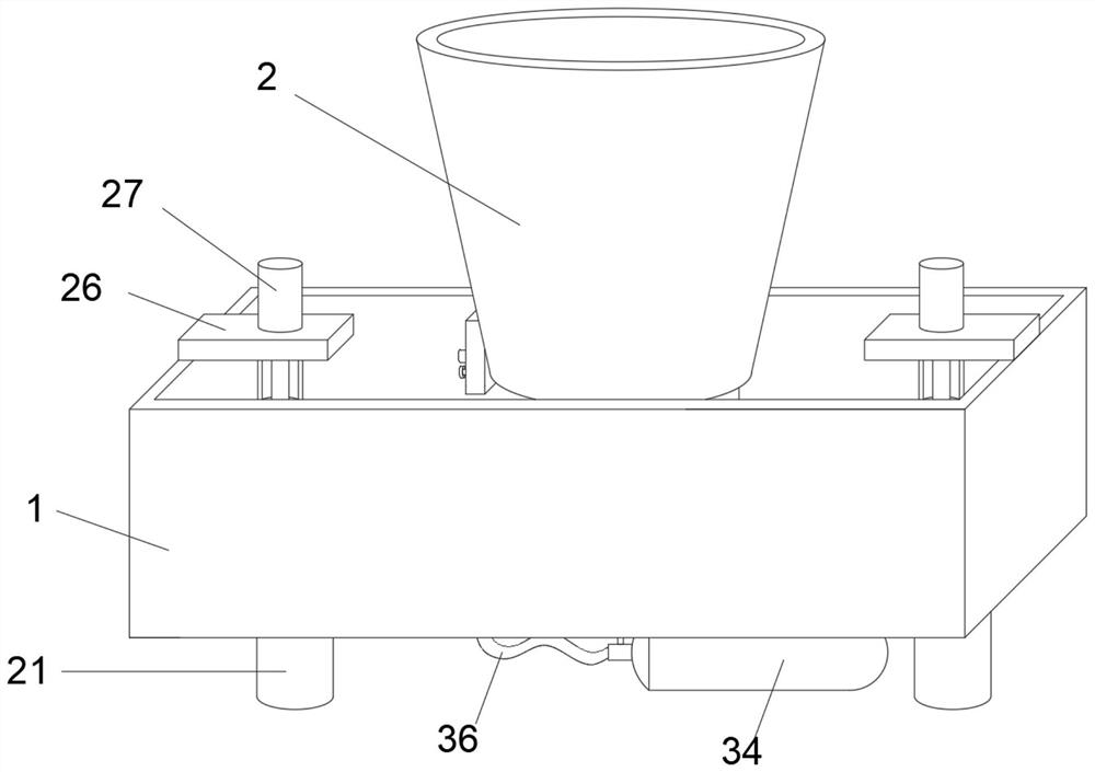
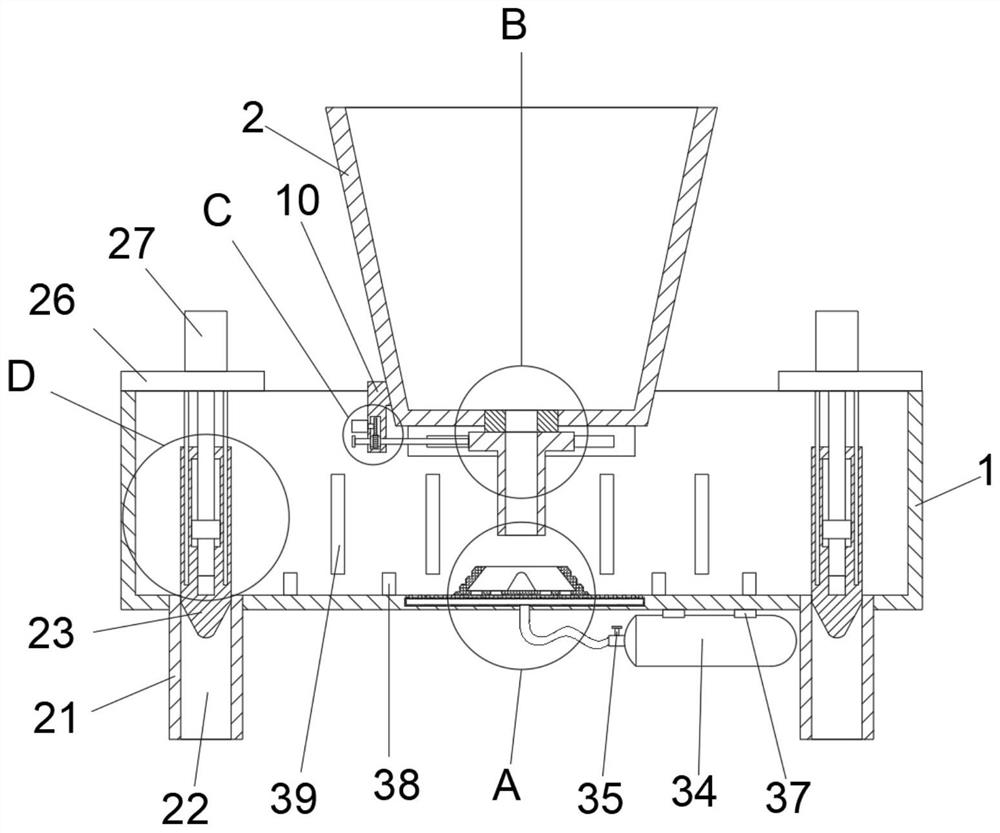
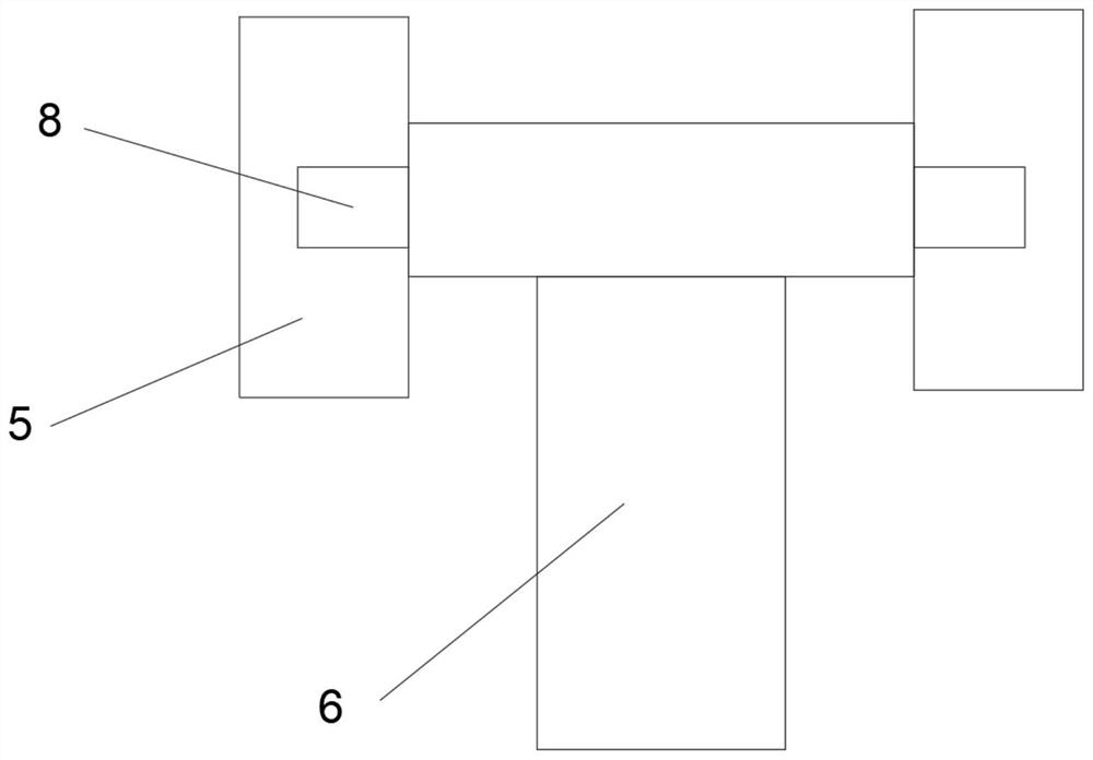
[0027] See Figure 1-7 The present invention provides a technical solution: a composite continuous casting in a package stabilizing system and a method of use, including the intermediate package 1 and the steel bag 2, the inside of the steel bag 2 is fixed to the joint 3, the discharge sleeve 3 The inside is opened with a pass groove 4, and the bottom symmetry of the steel bag 2 has a rail 5, and the inside of the rail 5 is slidably connected to the discharge tube 6, and the inside of the discharge tube 6 has a second channe...


PUM


Abstract

The invention discloses a composite continuous casting tundish flow stabilizing device and a using method thereof. The composite continuous casting tundish flow stabilizing device comprises a tundish and a steel ladle, wherein a discharge sleeve is fixedly connected to the interior of the steel ladle; a first through groove is formed in the discharge sleeve; sliding rails are symmetrically and fixedly connected to the bottom of the steel ladle; and a discharge pipe is connected to the interiors of the sliding rails in a sliding manner. The flow stabilizing device has the beneficial effects that: through the arrangement of a flow stabilizing base, a protruding block and a flow stabilizing groove, the impact force and the flow speed of molten steel are reduced, the effects of buffering and flow stabilizing of the molten steel flowing out of the steel ladle are achieved, and the flowing state of the molten steel is improved; through the arrangement of the discharge pipe and a first lead screw, the flow of the molten steel flowing out of the steel ladle is adjustable, and the flow can be blocked; through the arrangement of flow stabilizing columns, second lead screws and second threaded blocks, the flow of divided molten steel is adjustable; through the arrangement of first flow stabilizing plates and second flow stabilizing plates, the flowing rate of the molten steel is reduced, and the flow stabilizing effect is improved; and through the arrangement of a gas storage tank and a gas distributing pipe, an inert gas is filled, floating of impurities is facilitated, and the flowing condition of water flow is improved.

Description

Technical field [0001] The present invention relates to the field of continuous casting techniques, and in particular, a composite continuous casting stabilizing flow device and its use method thereof. Background technique [0002] Connecting is a referred to as continuous cast steel, in the process of producing various types of steel products in the steel plant, there are two methods using steel water coagulation forming: the traditional mold casting method and continuous cast steel method, and in the 1950s Continuous casting technology in Europe and the United States is a advanced technology that is directly casting the steel water. Compared with traditional methods, continuous casting technology has greatly improved the quality of metallic releasive rate and the quality of the slab, saving energy and other significant advantages, will be refined The steel bag of the steel water is transported to the retraining station. After the rotary table is turned to the casting position, ...

Claims


Application Information

Patent Timeline
IPC IPC(8): B22D41/00B22D37/00
CPCB22D41/00B22D37/00
Inventor 牟小海王东唐大友陈刚李志丹王刚
Owner 成渝钒钛科技有限公司
Why Eureka
Try Eureka