On-site welding process for steel structure

An on-site welding and steel structure technology, applied in welding equipment, welding accessories, manufacturing tools, etc., can solve problems such as uneven drying

Active Publication Date: 2021-07-06
广西天正钢结构有限公司
View PDF25 Cites 1 Cited by
  • Summary
  • Abstract
  • Description
  • Claims
  • Application Information

AI Technical Summary

Problems solved by technology

[0005]Aiming at the problems existing in the prior art, the purpose of the present invention is to provide a steel structure on-site welding process, which can realize the drying of welding rods used in conjunction with the process It can dry the welding rods needed for welding, and use the insulation cylinder to keep the dried welding rods warm and moisture-proof after the welding rods are dried, so as to avoid the moisture entering into the welding rods after the welding rods are used to affect the welding. As a result, compared with the prior art, multiple welding rods are placed in independent support

Method used


Image

  • On-site welding process for steel structure
  • On-site welding process for steel structure
  • On-site welding process for steel structure

Examples


Embodiment 1

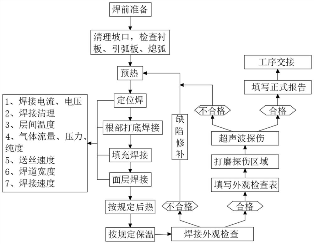
[0055] see figure 1 , a steel structure on-site welding process, comprising the following steps:

[0056] S1. Inspection before welding;

[0057] S2. Clean the groove after inspection;

[0058] S3. Check the lining plate, arc strike plate and arc extinguishing;

[0059] S4, preheating the steel structure;

[0060] S5. Dry the welding rod through the welding rod drying box, and use the dried welding rod to sequentially perform tack welding, root root welding, filling welding and surface layer welding on the steel structure;

[0061] S6. After the steel structure is welded, heat preservation is carried out after post-heat treatment;

[0062] S7. Check the welding appearance of the steel structure;

[0063] S8. The steel structure with qualified welding appearance is processed in the next step, and the steel structure with unqualified welding is repaired for defects and re-welded;

[0064] S9. Grinding the area to be detected by ultrasonic flaw detection;

[0065] S10, car...


PUM


Abstract

The invention discloses an on-site welding process for a steel structure, and belongs to the technical field of steel structure welding. A welding rod drying box matched with the process for use is arranged and can dry welding rods required during welding. After the welding rods are dried, a heat preservation cylinder is used for carrying out heat preservation and moisture insulation on the dried welding rods, and the situation that after the welding rods are taken, water enters the welding rods, and the welding effect is affected is avoided. Compared with the prior art, the multiple welding rods are arranged in independent supporting rods to be dried, the situation that drying is uneven due to the fact that the welding rods are stacked together is avoided. When the dried welding rods are taken out, the heat preservation cylinder is inserted into the inner side of a discharging groove, the dried welding rods can automatically fall to the inner side of the heat preservation cylinder, and the situation that when the welding rods are taken out, a frame body is opened, and heat in the frame body is lost is avoided. External humid air entering the frame body and the heat preservation cylinder is reduced as much as possible, and the drying effect of the welding rods and the using effect of the heat preservation cylinder are further improved.

Description

technical field [0001] The invention relates to the technical field of steel structure welding, and more specifically relates to an on-site welding process for steel structures. Background technique [0002] Welding manufacturing of steel structure begins with the preparation of welding production, which includes structural review, process plan and process specification design, process evaluation, preparation of process documents and quality assurance documents, ordering raw materials and auxiliary materials, outsourcing and self-made Design and manufacture assembly-welding equipment and equipment; then start the welding structure manufacturing process from material storage, including material re-inspection storage, material preparation and processing, assembly-welding, post-weld heat treatment, quality inspection, and product acceptance; interspersed Rework, finishing and painting; the whole process of final qualified product storage. [0003] When welding steel structures...

Claims


Application Information

Patent Timeline
IPC IPC(8): B23K9/00B23K9/235B23K9/32B23K31/12
CPCB23K9/00B23K9/235B23K9/32B23K31/125Y02P70/10
Inventor 谢振宇
Owner 广西天正钢结构有限公司
Why Eureka
Try Eureka