Method for improving wave resistance of amphibious aircraft based on active flow control technology

A technology of active flow control and amphibious aircraft, which is applied to seaplanes, aircraft, motor vehicles, etc., and can solve problems such as impact load on the body and large impact of water take-off and landing, poor adaptability of amphibious aircraft, hull roll, pitch, etc.

Inactive Publication Date: 2021-07-06
NANJING UNIV OF AERONAUTICS & ASTRONAUTICS
View PDF6 Cites 3 Cited by
  • Summary
  • Abstract
  • Description
  • Claims
  • Application Information

AI Technical Summary

Problems solved by technology

[0003] However, the adaptability of amphibious aircraft is poor in high sea conditions, and the hull is prone to violent roll...

Method used


Image

  • Method for improving wave resistance of amphibious aircraft based on active flow control technology
  • Method for improving wave resistance of amphibious aircraft based on active flow control technology
  • Method for improving wave resistance of amphibious aircraft based on active flow control technology

Examples


Embodiment 1

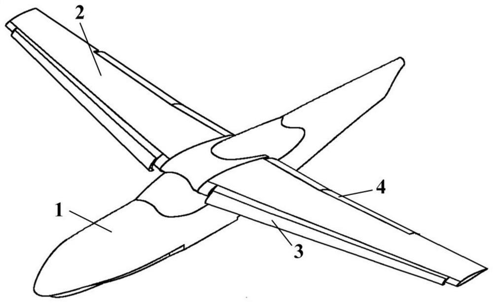
[0034] like Figure 1 to Figure 6 As shown, the embodiment of the present invention discloses a method for improving the anti-wave performance of an amphibious aircraft based on active flow control technology. "V-shaped" hull fuselage 1, upper single-swept wing 2, leading edge slat 3, trailing edge flap 4; the total length of the wing body assembly is 33.948m, and the wingspan is 42.03m; the verification The calculation conditions are the take-off state, the Mach number of the incoming flow is 0.2, and the altitude is 0km.

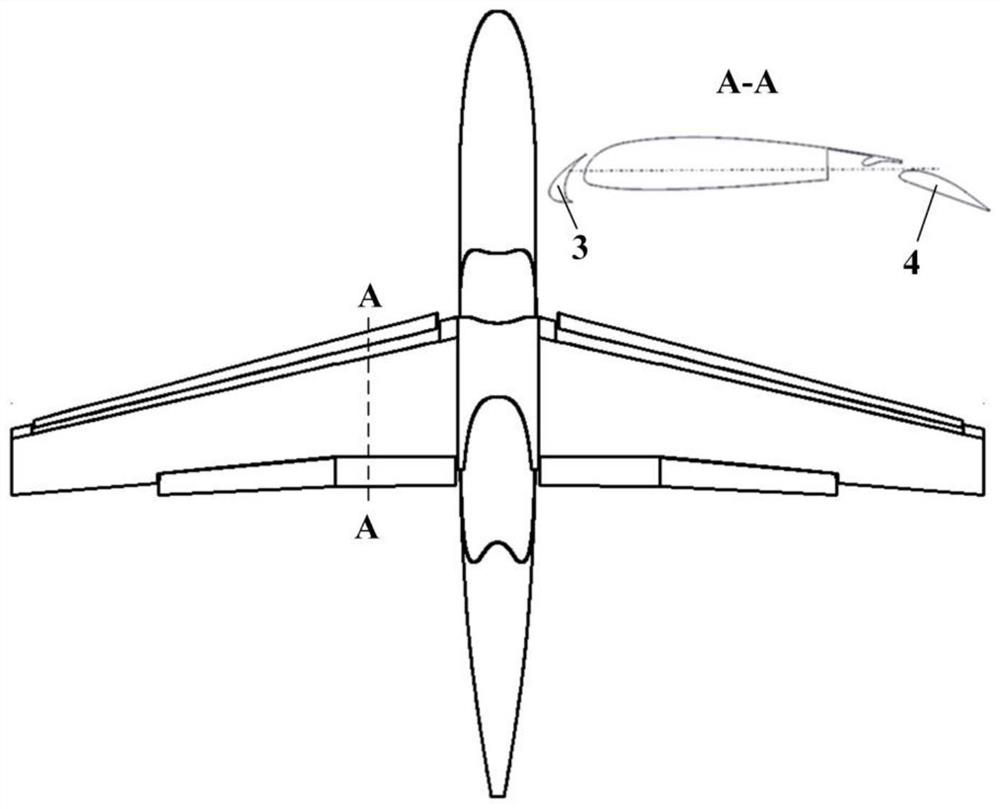
[0035] further, such as figure 2 As shown in the wing section, the basic lift device is composed of leading edge slats 3 and trailing edge flaps 4 . The relative chord length of the leading edge slat is 0.15, the slot width is 2%C, the overlap is 0.5%C, and the take-off state is deflected by 20°; The track width is 2%C, the overlap is 0.5%C, in the take-off state, the deflector does not protrude in the flap compartment, and the main flap is deflected b...

Embodiment 2

[0042] like Figure 7 ~ Figure 10 As shown, the present invention discloses another embodiment of a method for improving the anti-wave performance of an amphibious aircraft based on the active flow control technology. This embodiment mainly applies the active flow control technology to the vertical tail rudder surface, and its main structure includes : vertical tail stabilizer 6, rudder surface 7, air blow hole 5 and spacer 6.

[0043] further, such as Figure 7 As shown, the vertical tail 6 is a trapezoidal wing with a sweep angle of 32°, an aspect ratio of 1.35, and a trapezoidal ratio of 0.8; the vertical tail adopts a NACA symmetrical airfoil with a maximum thickness of 10%; the rudder 7 The relative area is 0.3, the maximum deflection angle is 20°; the calculation conditions are the take-off state, the rudder deflects 20°, the incoming flow velocity is the take-off speed 40m / s, the angle of attack is 0, and the altitude is 0km.

[0044] further, such as Figure 7 As sh...


PUM


Abstract

The invention provides a method for improving wave resistance of an amphibious aircraft based on the active flow control technology, a basic mechanical high lift device of the aircraft adopts a leading edge slat, a main wing and a trailing edge flap, a blow hole is arranged at a hinge of the trailing edge flap, and high-pressure airflow of an engine is guided to be blown to the surface of the flap through a pipeline system, so that the wave resistance of the amphibious aircraft is improved. The inner blowing type flap is formed; similarly, an air blowing hole is formed in the hinge position of the control surface of the empennage, a small engine arranged in the empennage generates high-pressure airflow, and the high-pressure airflow is guided to be blown to the control surface through a pipeline. By means of the active flow control technology, lift augmentation and empennage and control surface benefits are achieved more efficiently, the lift coefficient of the amphibious aircraft in the take-off and landing stage is increased to the maximum extent, and the wave resistance of the amphibious aircraft is improved by reducing the take-off and landing speed and the take-off and landing skating distance and guaranteeing the stable maneuverability.

Description

technical field [0001] The invention relates to the technical field of short take-off and landing of fixed-wing aircraft, in particular to a method for improving the anti-wave performance of amphibious aircraft based on active flow control technology. Background technique [0002] An amphibious aircraft is an aircraft equipped with a buoy or hull adapted to land, take off and operate on water. Amphibious aircraft have attracted extensive attention from domestic and foreign aviation circles due to their civil uses such as sea rescue, forest fire fighting, and transportation, as well as their unique strategic position in military affairs that can undertake maritime reconnaissance, anti-submarine, and bombing. Among them, the typical medium and large amphibious aircraft The aircraft include Russia's Be-200, Japan's US-2, etc., as well as my country's AG-600, which has successfully completed test flights recently. [0003] However, the adaptability of amphibious aircraft is poor...

Claims


Application Information

Patent Timeline
IPC IPC(8): B64C35/00
CPCB64C35/006B64C35/001B64C35/008
Inventor 肖天航朱震浩支豪林
Owner NANJING UNIV OF AERONAUTICS & ASTRONAUTICS
Why Eureka
Try Eureka