Remote multi-ATE semiconductor test equipment synchronization method and system and test method

A test equipment and long-distance technology, applied in time division multiplexing systems, transmission systems, synchronization devices, etc., can solve problems such as poor signal quality and integrity, unsuitable transmission, and electrical signal attenuation

Pending Publication Date: 2021-07-06
杭州加速科技有限公司
View PDF0 Cites 1 Cited by
  • Summary
  • Abstract
  • Description
  • Claims
  • Application Information

AI Technical Summary

Problems solved by technology

In order to achieve this goal, the clock and trigger signal sources are usually sent to multiple test equipment through electrical signals in the current technology, so as to realize the clock synchronization and trigger synchronization between multiple test equipment; however, the electrical si...

Method used


Image

  • Remote multi-ATE semiconductor test equipment synchronization method and system and test method
  • Remote multi-ATE semiconductor test equipment synchronization method and system and test method
  • Remote multi-ATE semiconductor test equipment synchronization method and system and test method

Examples


Embodiment 1

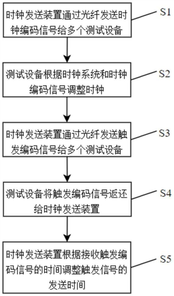
[0053] This embodiment proposes a method for synchronizing long-distance multi-ATE semiconductor test equipment, which transmits clock signals and trigger signals through high-speed optical fibers, so as to maintain high-precision testing requirements even during long-distance testing. The specific plan is as follows:

[0054] A synchronization method for long-distance multi-ATE semiconductor test equipment, including two parts: clock synchronization and trigger synchronization. On the basis of the original equipment test method, the electrical port used to transmit the clock signal and trigger signal is removed, and the clock signal and trigger signal are transmitted through high-speed optical fiber. The trigger signal, without increasing the cost of testing, breaks through the previous limitation that optical fibers are only used to transmit data. For details, please refer to the attached manual figure 1 shown, including the following steps:

[0055] S1. The clock sending ...

Embodiment 2

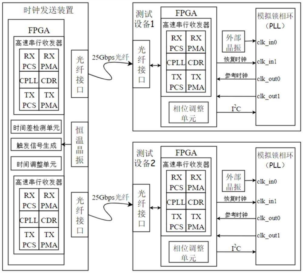
[0068] On the basis of Embodiment 1, this embodiment proposes a long-distance multi-ATE semiconductor testing equipment synchronization system, which systematizes the long-distance equipment testing method proposed in Embodiment 1. The specific structure is attached to the manual image 3 As shown, the scheme is as follows:

[0069] A long-distance device testing system includes a clock sending device, a high-speed optical fiber and a plurality of testing devices. The clock sending device is connected to a plurality of testing devices through the high-speed optical fiber. Both the clock sending device and the testing device are provided with high-speed optical fiber interfaces. In this embodiment, 25Gbps high-speed optical fiber is preferred for transmitting clock coded signals and trigger coded signals, so as to realize high-precision long-distance synchronous clock and synchronous trigger targets.

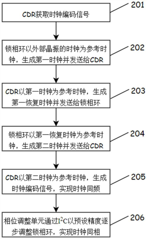
[0070] The clock sending device is used to send clock coded signals and tri...

Embodiment 3

[0077] This embodiment proposes a test method for long-distance multi-ATE semiconductor test equipment, which is suitable for ATE semiconductor test equipment. The specific plan is as follows:

[0078] A test method for long-distance multi-ATE semiconductor test equipment, including clock synchronization and trigger synchronization, wherein the clock synchronization includes:

[0079] The clock sending device sends the clock coded signal embedded with the clock signal to a plurality of test equipment through the high-speed optical fiber, and each test device adjusts the clock according to the clock coded signal to be consistent with the clock of the clock sending device.

[0080] Trigger synchronization includes:

[0081] The clock sending device sends the trigger code signal embedded with the trigger signal to multiple test equipment through high-speed optical fiber, and adjusts the time to send the trigger code signal until multiple test equipment receive the trigger code s...


PUM


Abstract

The invention provides a remote multi-ATE semiconductor test equipment synchronization method and system and a test method. The synchronization method comprises the following steps: a clock sending device sends a clock coding signal embedded with a clock signal to a plurality of test equipment through a high-speed optical fiber; the test equipment receives the clock coding signal, recovers clocks, and adjusts the clocks of the test equipment to be consistent with the clock of the clock sending device according to a clock adjustment system; the clock sending device sends a trigger coding signal embedded with a trigger signal to the plurality of test equipment through the high-speed optical fiber; the test equipment receives the trigger coding signal and returns the trigger coding signal to the clock sending device through the high-speed optical fiber; and the clock sending device adjusts the time point of sending the trigger coding signal according to the time difference in receiving the trigger coding signal. According to the invention, a 25Gbps high-speed optical fiber is used for transmitting signals, so that high-precision and long-distance synchronous clock and synchronous target triggering among the plurality of semiconductor test equipment are realized, and the system has the characteristics of long synchronous distance, low cost and high precision.

Description

technical field [0001] The invention relates to the field of ATE semiconductor testing equipment, and specifically provides a synchronization method, system and testing method for long-distance multi-ATE semiconductor testing equipment. Background technique [0002] The development of many modern technologies is inseparable from the progress of testing technology, which is the source technology of information. With the development of the times, people's requirements for the accuracy of the obtained information are gradually increasing, and the simple independent test and centralized test can no longer meet the needs of modern test technology. [0003] ATE (Automatic Test Equipment) is automatic test equipment, which is a system for automatic testing of integrated circuits through computers and special equipment. ATE semiconductor test equipment is used to test the integrity of integrated circuit functions and performance, and is an important equipment to ensure the quality ...

Claims


Application Information

Patent Timeline
IPC IPC(8): H04J3/06H04L7/033
CPCH04J3/0638H04L7/033
Inventor 陈永邬刚
Owner 杭州加速科技有限公司
Why Eureka
Try Eureka