
Metal plate drilling cutter

A drilling tool and sheet metal technology, which is applied in drilling/drilling equipment, drill repairing, drilling tool accessories, etc., can solve the problem of not being able to effectively ensure the smoothness of the edge of the cutting hole

Inactive Publication Date: 2021-07-09
江苏大东精密机械有限公司
View PDF1 Cites 1 Cited by
  • Summary
  • Abstract
  • Description
  • Claims
  • Application Information

AI Technical Summary

Problems solved by technology

[0005] Although this multi-functional sheet metal processing equipment can absorb the debris generated by the drilling through the action of the dust suction mechanism and the telescopic tube during the drilling process, it can prevent the dust from flying in the air and play a role The effect of staff protection, but often cannot effectively ensure the smoothness of the edge of the cutting hole during the cutting process

Method used


Image

  • Metal plate drilling cutter
  • Metal plate drilling cutter

Examples


Embodiment Construction

[0025] The specific embodiments of the present invention will be further described below in conjunction with the accompanying drawings.

[0026] The technical scheme adopted in the present invention is:

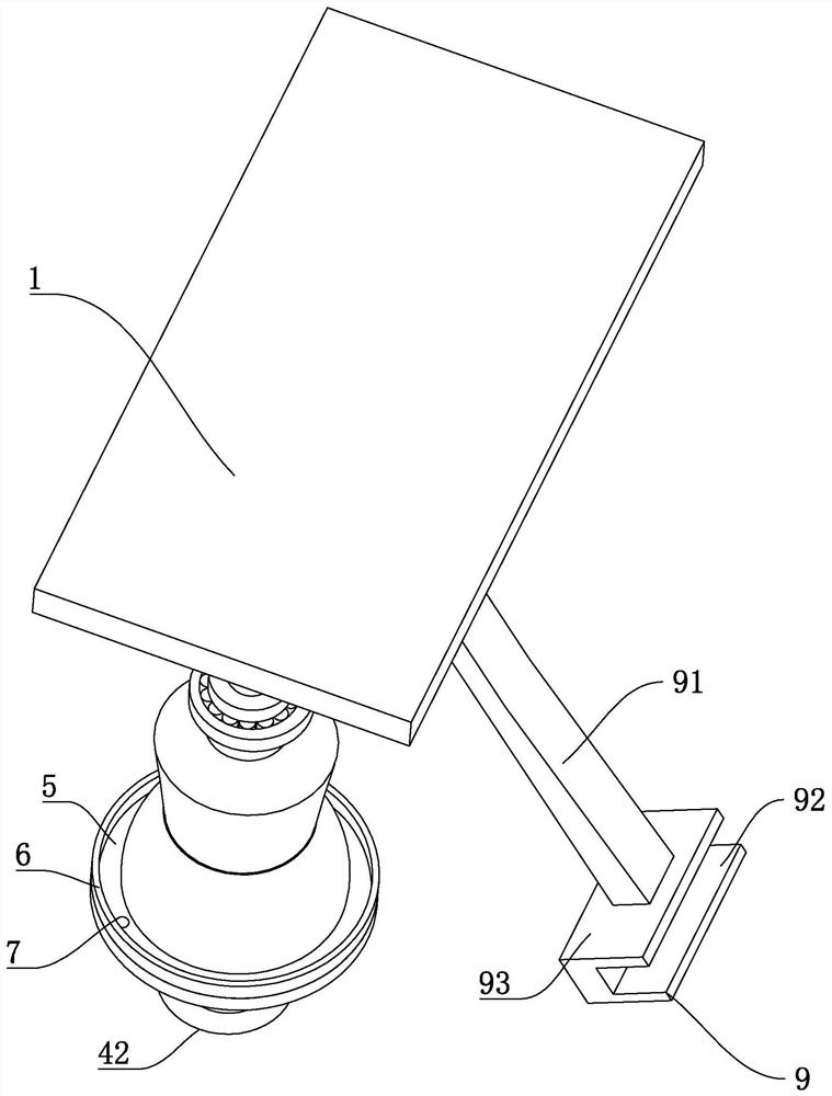
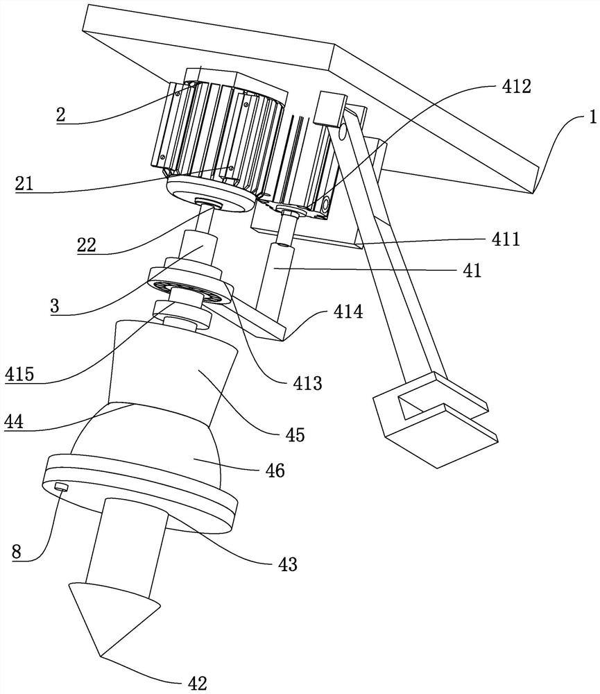
[0027] A sheet metal drilling tool, such as figure 1 and figure 2 Shown, comprise base 1, base 1 is provided with rotating device 2, and rotating device 2 comprises the rotating cylinder 21 that is positioned at base 1 and is positioned at cylinder exit and is provided with the support bar 22 that is connected with elevating device 41, is provided with on rotating device 2 Telescopic rod 3 is arranged, and telescopic rod 3 tops are provided with drilling device 4, and drilling device 4 comprises the elevating device 41 that is provided with on one side of telescopic rod 3, is provided with conical drill bit 42 at telescopic rod 3 top, and conical drill bit 42 There is also a transition rod 43 between the telescopic rod 3, and a grinding drill 44 is also connected to the tr...


PUM


Abstract

The invention discloses a metal plate drilling cutter, and aims to provide a metal plate drilling cutter capable achieving drilling conveniently. According to the technical scheme, the metal plate drilling cutter is characterized by comprising a base, a rotating device is arranged on the base, a telescopic rod is arranged on the rotating device, a drilling device is arranged at the top end of the telescopic rod, and the drilling device comprises a lifting device arranged on one side of the telescopic rod; and a conical drill bit is arranged at the top end of the telescopic rod, a transition rod is further arranged between the conical drill bit and the telescopic rod, a grinding drill bit is connected to the transition rod, and the grinding drill bit comprises a circular table base close to one end of the telescopic rod and an arc-shaped dull polish device located at the top end of the circular table base.

Description

technical field [0001] The invention relates to the field of sheet metal cutting equipment, in particular to a sheet metal drilling knife. Background technique [0002] Drilling is the process of machining a hole in a solid material, and the diameter of the hole is generally less than 80mm. Drills usually have two main cutting edges where the bit is cut as it rotates. The rake angle of the drill increases from the central axis to the outer edge, the cutting speed of the drill near the outer circle is higher, the cutting speed decreases toward the center, and the cutting speed of the rotation center of the drill is zero. [0003] The transverse edge of the drill bit is located near the axis of rotation, the front angle of the transverse edge is large, there is no chip space, and the cutting speed is low, resulting in greater axial resistance. If the transverse cutting edge is ground into A or C type in DI1414, and the cutting edge close to the central axis has a positive ra...

Claims


Application Information

Patent Timeline
Patent Type & Authority Applications(China)
IPC IPC(8): B23P23/04B23B47/20B23B47/22B23B51/08B23Q1/26
CPCB23B51/08B23P23/04B23Q1/26B23Q5/26B23Q5/28
Inventor 郭建栋
Owner 江苏大东精密机械有限公司
Learn More