Drilling machine beneficial for cleaning up scraps

A drilling machine and drill bit technology, applied in the direction of boring/drilling, drilling/drilling equipment, clamping, etc., can solve the problems of random flying of debris, damage of staff, attachment of staff, etc., and achieve a large contact area , Improve the strength and improve the effect of precision

Pending Publication Date: 2021-07-09
李胜强
View PDF6 Cites 3 Cited by
  • Summary
  • Abstract
  • Description
  • Claims
  • Application Information

AI Technical Summary

Problems solved by technology

[0003] According to a combined drilling machine disclosed in Chinese Patent No. CN111215655A, by adding an empty pipe support device on the bed body to replace the traditional clamp, it can support the inside of the hollow pipe and make up for the shortcoming that the hollow pipe is easy to collapse and be damaged as a hollow structure. To prevent the hollow tube from breaking, it can not only adapt to the needs of drilling holes with different distances, but also can adapt to hollow tubes with different diameters. At the same time, it can drive the hollow tube to rotate, rotate the surface of the drilled hole, and rotate the surface to be drilled to the bottom of the drill bit without manual rotation, which further improves the drilling efficiency. Random flying during the drilling process is very unfavorable for the cleaning work after use, and in the state of splashing debris, it is easy to attach to the outer clothing of the operator or cause damage to the staff
[0004] To sum up, the debris flies randomly during the drilling process, which is not conducive to the cleaning work after use, and in the state of splashing debris, it is easy to attach to the outer clothing of the operator or cause damage to the staff

Method used


Image

  • Drilling machine beneficial for cleaning up scraps
  • Drilling machine beneficial for cleaning up scraps
  • Drilling machine beneficial for cleaning up scraps

Examples


Embodiment 1

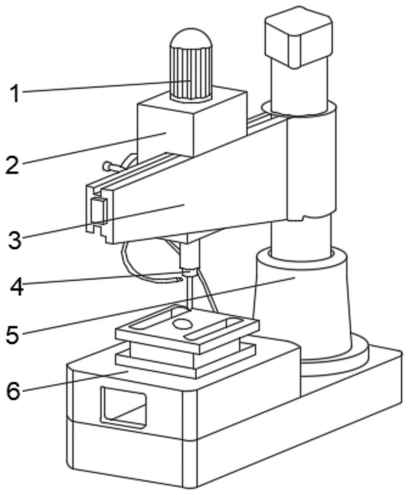
[0033] see Figure 1-2 , the present invention provides a technical solution: a drilling machine for cleaning waste, including a support frame 5, a movable frame 3 is arranged on the outer wall of the middle part of the support frame 5, and a controller 2 is arranged on the middle part of the back of the movable frame 3, and the controller 2 There is a motor 1 on the top, the output shaft of the motor 1 runs through the controller 2 and extends to the inside of the controller 2, the middle position of the bottom of the controller 2 is fixedly connected with the drill bit 4, and the right side of the top of the support frame 5 is located under the drill bit 4 A collecting device 6 is fixedly connected.

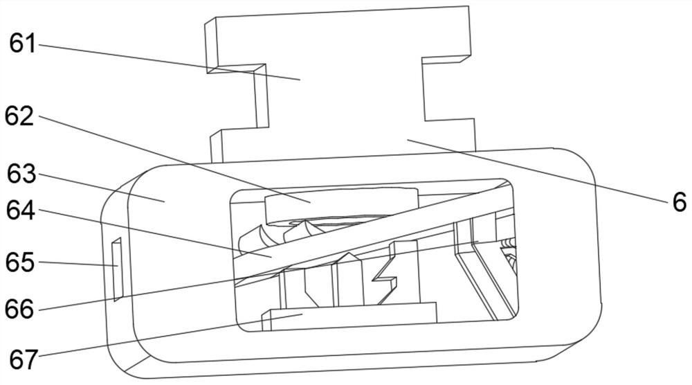
[0034]Wherein, the collection device 6 includes a collection box 63, the top middle of the collection box 63 is fixedly connected with a clamp 61, the top of the inner cavity of the clamp 61 is provided with a flow groove 62, and the bottom of the flow groove 62 runs through th...

Embodiment 2

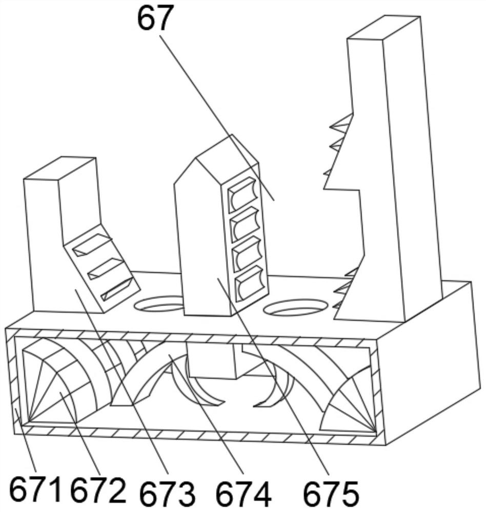
[0037] see Figure 1-4 , on the basis of Embodiment 1, the present invention provides a technical solution: the auxiliary mechanism 67 includes an outer frame 671, a separation mechanism 675 is provided at the top middle of the outer frame 671, and the bottom of the separation mechanism 675 penetrates the outer frame 671 and extends to Inside the outer frame 671, the bottom of the inner chamber of the outer frame 671 is located on both sides of the separation mechanism 675 and is fixedly connected with an auxiliary frame 674, and the bottom of the inner wall on both sides of the outer frame 671 is fixedly connected with a blocking block 672, and the top of the outer frame 671 is located at the separation mechanism. Vibrating plates 673 are fixedly connected to both sides of 675 .

[0038] Wherein, the separation mechanism 675 includes a contact block d1, the top of the inner cavity of the contact block d1 is fixedly connected with a receiving block d2, the top of the contact b...

Embodiment 3

[0041] see Figure 1-5 , on the basis of Embodiment 1 and Embodiment 2, the present invention provides a technical solution: the guide mechanism d6 includes a guide block d61, the inner walls of both sides of the guide block d61 are fixedly connected with a middle solid block d62, and the top of the middle solid block d62 A combination block d63 is fixedly connected, the bottom of the combination block d63 is located on both sides of the middle solid block d62, and a reset block d64 is fixedly connected, and the right side of the inner cavity bottom of the combination block d63 is fixedly connected with a force plate d65.

[0042] When in use, the guide block d61 can be installed to increase the contact area, and at the same time, it is not easy to incline at an angle. It can not bend after being broken under a large pressure, which further improves the accuracy of drilling work, thereby increasing the surface. The contact area is conducive to the further fixing of the device,...


PUM


Abstract

The invention discloses a drilling machine beneficial for cleaning up scraps. The drilling machine comprises a supporting frame, wherein a moving frame is arranged on the outer wall of the middle of the supporting frame, a controller is arranged in the middle of the back face of the moving frame, a motor is arranged at the top of the controller, a drill bit is fixedly connected to the middle of the bottom of the controller, and a collecting device is fixedly connected to the position, below the drill bit, of the right side of the top of the supporting frame. The invention relates to the technical field of drilling machines. According to the drilling machine beneficial for cleaning up the scraps, the phenomena that the scraps splash everywhere in the drilling process, the working environment is polluted, and cleaning is not facilitated are avoided, a leakage plate is provided with interception teeth, and fine filtering holes are formed in the leakage plate, so that the scraps in the device can be contacted and separated, a workpiece is further cooled, the drilling deviation caused by too high temperature generated in the drilling process is avoided, deformation caused by adhesion of scrap iron on the surface of a friction workpiece is effectively avoided, and the situation that scraps adhere to the interior of a circulation groove and are not convenient to clean up is further avoided.

Description

technical field [0001] The invention relates to the technical field of drilling machines, in particular to a drilling machine for cleaning waste chips. Background technique [0002] Drilling machine refers to a machine tool that mainly uses a drill bit to process holes on a workpiece. Usually, the rotation of the drill bit is the main movement, and the axial movement of the drill bit is the feed movement. The drilling machine has a simple structure and relatively low machining accuracy. It can drill through holes, blind holes, and replace special tools. , can be expanded, countersinked, reamed or tapped. Drilling machine is a universal machine tool with a wide range of uses. When equipped with process equipment on the drilling machine, it can also perform boring. Equipped with a universal workbench on the drilling machine can also Drilling, reaming, and reaming; the drilling machine mainly uses a drill bit to process holes (such as drilling, reaming, reaming, tapping, counte...

Claims


Application Information

Patent Timeline
Patent Type & Authority Applications(China)
IPC IPC(8): B23Q11/00B23Q11/10B23Q3/06B23Q3/10B23B39/00
CPCB23Q11/0042B23Q11/10B23Q3/064B23Q3/10B23B39/00
Inventor 不公告发明人
Owner 李胜强
Why Eureka
Try Eureka