A swirl flood discharge tunnel that reduces the velocity at the outlet of the swirl tunnel

A flood discharge tunnel and flow velocity technology, which is applied in hydroelectric power stations, coastline protection, sea area engineering, etc., can solve problems such as turbulence, corrosion of diversion tunnel outlet flow state, etc., to reduce water surface height difference, weaken backwater phenomenon, thickness increased effect

Active Publication Date: 2022-07-19
POWERCHINA XIBEI ENG
View PDF0 Cites 0 Cited by
  • Summary
  • Abstract
  • Description
  • Claims
  • Application Information

AI Technical Summary

Problems solved by technology

[0004] In order to overcome the problems of severe corrosion and disordered outlet flow in existing diversion tunnels, the present invention provides a swirl flood discharge tunnel that reduces the flow velocity at the outlet of the swirl tunnel. The diversion pier is used to improve the flow state of the water flow, to ensure that the inner wall of the diversion tunnel will not be eroded by excessive water flow, and to improve the service life of the diversion tunnel

Method used


Image

  • A swirl flood discharge tunnel that reduces the velocity at the outlet of the swirl tunnel
  • A swirl flood discharge tunnel that reduces the velocity at the outlet of the swirl tunnel
  • A swirl flood discharge tunnel that reduces the velocity at the outlet of the swirl tunnel

Examples


Embodiment 1

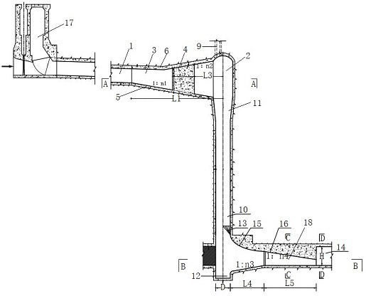
[0026] In order to overcome the problems of serious corrosion of the existing diversion holes and turbulent outlet flow state, the present invention provides such as Figure 1-5 As shown in a swirl flood discharge tunnel that reduces the flow velocity at the outlet of the swirl tunnel, the present invention adopts the expansion body connection section to reduce the flow velocity at the bottom of the flood discharge tunnel, and adopts the diverter pier to improve the flow state of the water flow, so as to ensure that the inner wall of the diversion tunnel will not be damaged. Excessive water erosion improves the service life of the diversion hole.

[0027] A swirl flood discharge tunnel that reduces the flow velocity at the outlet of the swirl tunnel, including a sluice lock chamber 17, a water diversion tunnel 1, a vortex chamber 2, a vertical shaft 10, an expanded body connecting section, a stilling pool 12 and a diversion hole 14. The upstream of the diversion tunnel 1 is co...

Embodiment 2

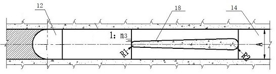
[0030] On the basis of Embodiment 1, in this embodiment, preferably, the expanded body connecting section includes a vertical section 13 , a turning section 15 and a pressure slope section 16 , and the vertical section 13 and the pressure slope section 16 Connected by the turning section 15, the width of the side wall of the turning section 15 and the pressure slope section 16 is the same as the width A of the diversion hole 14; the vertical section 13 gradually transitions from the semicircle of the shaft to the shape of a round arch on the outside and a straight line on the inside; The top arch of the turning section 15 takes the end of the vertical section 13 as the starting point and transitions to the starting point of the pressure slope section 16 in the form of a 1 / 4 ellipse major axis turn, wherein the ellipse equation is , a, b are determined according to the diversion hole width A, a value is (1 ~ 3) A, b is (0.3 ~ 1) a; the bottom of the turning section 15 adopts a ...

Embodiment 3

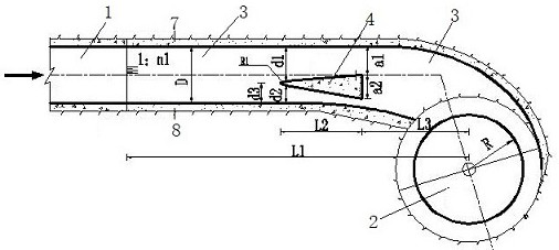
[0044] On the basis of Embodiment 1 or 2, in this embodiment, preferably, the thickness of the side wall 17 is 50cm; the width D of the bottom plate 5 is 680cm, the slope ratio of the bottom plate 5 is 1:7.4, and the slope ratio of the slope section of the top arch 6 is 1:8.6, the radius R of the vortex chamber 2 is 500cm, the distance a1 between the backwater surface and the side wall 17 of the transition section 3 is 300cm, the width a2 of the backwater surface is 300cm, the arc radius R1 of the waterfront surface is 150cm, and the sidewalls 1 and 7 of the waterfront surface are The distance between the wall 17 is d1 is 410cm, the distance d2 between the side wall 2 and the side wall 28 is 195cm, the distance between the central axis of the waterfront surface and the side wall 28 is d3 240cm, the bottom plate 5 The distance between the slope point and the center line of the vortex chamber 2 is L1 is 4800cm, the length L2 of the water dividing wall 4 along the flow is 1500 cm,...


PUM


Abstract

The invention provides a swirl flood discharge tunnel for reducing the flow velocity at the outlet of the swirl tunnel, comprising a sluice lock chamber, a water diversion tunnel, a vortex chamber, a vertical shaft, an expanded body connecting section, a stilling pool and a diversion tunnel. It is connected with the sluice chamber, the downstream of the diversion tunnel and the vortex chamber are connected by a transition section, and the transition section is provided with a water dividing wall; the lower end of the vortex chamber is connected with the vertical shaft through the vertical shaft connecting section, so the The expanded body connecting section communicates the lower part of the shaft with the diversion hole, and one end of the diversion hole is blocked; the expansion body connecting section is provided with a diverter pier, and the stilling pool is arranged at the bottom of the shaft. In the invention, the water flow passes through the transition section and the water dividing wall, so that the thickness of the rotating water flow in the vortex chamber is increased, the water surface climb is greatly reduced, and the water surface height difference of the rotating water flow in the vortex chamber is also reduced. After the water flow reaches the stilling pool, the stagnant water phenomenon of the hydraulic jump is weakened by the expansion body connection section and the energy dissipation space of the swirling pressure flow is increased.

Description

technical field [0001] The invention belongs to the technical field of swirl energy dissipation of water conservancy and hydropower projects, and particularly relates to a swirl flood discharge tunnel for reducing the flow velocity at the outlet of the swirl tunnel. Background technique [0002] The diversion facilities of hydropower projects in the canyon area generally use diversion tunnels with flow-off cofferdams. Due to the abundant flood flow of rivers in western my country, the scale of diversion tunnels is often large. The specific performance is that the diversion tunnels have large cross-sections and a large number of diversion tunnels. The corresponding project investment of each diversion tunnel is 100 to 200 million yuan. Therefore, after the diversion function is completed, it is of great economic value to convert the temporary structure of the diversion tunnel into a permanent water discharge structure, and it is also conducive to optimizing the layout of the ...

Claims


Application Information

Patent Timeline
Patent Type & Authority Patents(China)
IPC IPC(8): E02B9/04E02B8/06
CPCE02B9/04E02B8/06Y02E10/20
Inventor 周恒刘静狄圣杰陆希丁新潮王卫国卫勇
Owner POWERCHINA XIBEI ENG
Why Eureka
Try Eureka