A kind of functional fabric production equipment and its process

A production equipment and functional technology, applied in the textile field, can solve problems such as fiber waste, achieve the effect of improving comfort and reducing waste

Active Publication Date: 2022-05-20
杭州得力纺织有限公司
View PDF9 Cites 0 Cited by
  • Summary
  • Abstract
  • Description
  • Claims
  • Application Information

AI Technical Summary

Problems solved by technology

[0005] The purpose of the present invention is to provide a functional fabric production equipment for the deficiencies of the prior art. By setting up a waste recovery unit behind the drying unit, the unglued fibers in the drying process can be recovered in a concentrated manner and transported to the sizing machine at regular intervals. The unit reuse solves the technical problem of fiber waste, and the hot air from the dehumidification unit and the output from the carding unit are recycled and reused by the pipeline to reduce energy waste

Method used


Image

  • A kind of functional fabric production equipment and its process
  • A kind of functional fabric production equipment and its process
  • A kind of functional fabric production equipment and its process

Examples


Embodiment 1

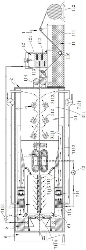
[0063] Such as figure 1 As shown, a functional fabric production equipment includes a sizing unit 1, a box body 2 connected to the tail end of the sizing unit 1, a dehumidification unit 3 arranged in the box body 2, a carding unit 4, a drying unit 5, Waste recycling unit 6, heating unit 7 and traction unit 8 located at one end of box body 2; said traction unit 8 includes a drive motor, a drive chain and a number of discharge rollers;

[0064] Both ends of the box body 2 are respectively provided with a feed port 21 and a discharge port 22;

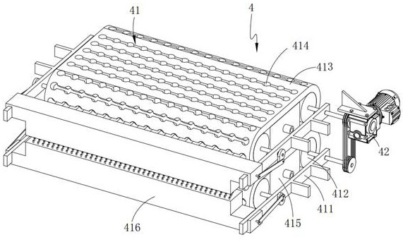
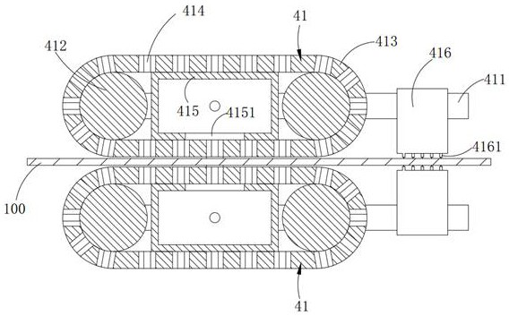
[0065] The carding unit 4 includes two sets of carding assemblies 41 arranged symmetrically up and down, and a drive assembly 42 and an adsorption assembly 43 connected to the two sets of carding assemblies 41;

[0066] Such as figure 1 As shown, the drying unit 5 includes an upper drying box and a lower drying box, the bottom of the upper drying box is provided with a number of air outlets a; the top of the lower drying box is provided ...

Embodiment 2

[0100] The production process of using a functional fabric production equipment described in the first technical solution of the above embodiment for producing functional fabrics includes the following steps:

[0101] Step 1, the fabric reel is fixed, the fabric 100 reel to be sized is fixed on the unwinding support 112, and the fabric 100 is pulled forward by using the traction system;

[0102] Step 2, slurry preparation, adding the fiber 200 into the mixing tank 121 in proportion, using the stirring paddle 122 to stir the slurry in the mixing tank 121, and adding it to the sizing tank 111 after the stirring is completed;

[0103] Step 3, sizing, when the fabric 100 passes through the sizing pool 111, the surface of the fabric 100 is subjected to sizing treatment; the fabric 100 is flattened by a flattening roller, and the excess material on the fabric 100 is extruded by a squeeze roller arranged behind the flattening roller. slurry, and simultaneously press the fiber 200 deb...


PUM


Abstract

The invention provides a functional fabric production equipment, comprising a sizing unit, a box body connected to the tail end of the sizing unit, a dehumidification unit, a carding unit, a drying unit, a waste material recovery unit, and a heating unit sequentially arranged in the box body And the traction unit located at one end of the box; by setting a waste recycling unit behind the drying unit, the fibers that are not glued in the drying process are collected and recycled and regularly transported to the sizing unit for reuse, which solves the technical problem of fiber waste. The pipeline recycles the hot air from the dehumidification unit and the hot air output from the carding unit to reduce energy waste.

Description

technical field [0001] The invention relates to the technical field of textiles, in particular to functional fabric production equipment and a process thereof. Background technique [0002] People's living standards continue to improve, and ordinary fabrics cannot meet the requirements of different environments, such as functional fabrics such as quick-drying fabrics, waterproof fabrics, and flame-retardant fabrics. With the development of material technology, different functional fabrics have emerged, among which production The fiber requirements used in sizing in the process are also getting higher and higher, and the price of fibers is also very expensive. [0003] Chinese patent CN201110256017.X discloses a fabric sizing machine, which is used for sizing and drying fabrics. The fabrics enter the sizing tank through unwinding rollers, drive rollers and sizing rollers in turn; the sizing rollers are located in the sizing tank. Inside; there is a gap between the pair of sq...

Claims


Application Information

Patent Timeline
Patent Type & Authority Patents(China)
IPC IPC(8): F26B13/00F26B13/14F26B21/02F26B25/00F26B25/18
CPCF26B13/00F26B13/14F26B21/02F26B25/003F26B25/18Y02P70/10
Inventor 邵金环周洪
Owner 杭州得力纺织有限公司
Why Eureka
Try Eureka