
A light pressure measuring device

A measurement device, piezoelectric technology, applied in the field of sensors, can solve the problem of low precision, achieve the effect of improving measurement accuracy, high precision, and easy to measure accurately

Active Publication Date: 2022-08-05
UNIV OF ELECTRONICS SCI & TECH OF CHINA
View PDF5 Cites 0 Cited by
  • Summary
  • Abstract
  • Description
  • Claims
  • Application Information

AI Technical Summary

Problems solved by technology

[0005] Aiming at the above-mentioned deficiencies in the prior art, a light pressure measurement device provided by the present invention solves the problem of low precision of the existing light pressure measurement method

Method used


Image

  • A light pressure measuring device
  • A light pressure measuring device
  • A light pressure measuring device

Examples


Embodiment Construction

[0028]The specific embodiments of the present invention are described below to facilitate those skilled in the art to understand the present invention, but it should be clear that the present invention is not limited to the scope of the specific embodiments. For those skilled in the art, as long as various changes Such changes are obvious within the spirit and scope of the present invention as defined and determined by the appended claims, and all inventions and creations utilizing the inventive concept are within the scope of protection.

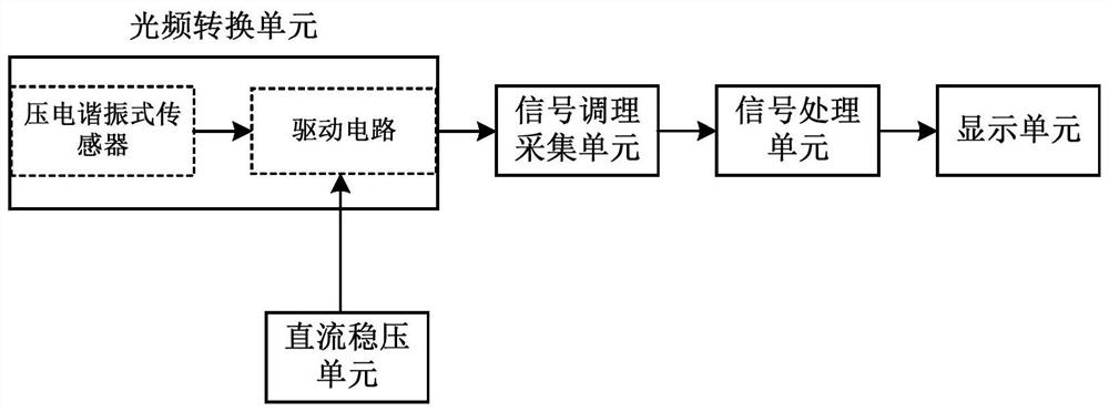
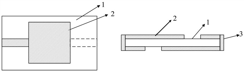
[0029] like figure 1 and figure 2 As shown, the optical pressure measurement device includes an optical frequency conversion unit, a signal conditioning acquisition unit, a signal processing unit, a display unit and a DC voltage stabilization unit;

[0030] The optical frequency conversion unit includes a drive circuit and a piezoelectric resonance sensor; the output end of the piezoelectric resonance sensor is connected with the input en...


PUM


Abstract

The invention discloses an optical pressure measurement device, which comprises an optical frequency conversion unit, a signal conditioning acquisition unit, a signal processing unit, a display unit and a DC voltage stabilization unit; the optical frequency conversion unit includes a drive circuit and a piezoelectric resonance sensor; The output end of the electric resonance sensor is connected with the input end of the drive circuit; the output end of the drive circuit is connected in communication with the input end of the signal conditioning and acquisition unit; the signal processing unit is respectively connected with the output end of the signal conditioning and acquisition unit and the display unit in communication; The voltage stabilization unit is electrically connected with the driving circuit; the piezoelectric resonance sensor includes: a sensor wafer, a first sensor electrode and a second sensor electrode; the sensor wafer is fixed between the first sensor electrode and the second sensor electrode. The invention improves the optical pressure measurement accuracy by converting the optical signal into the frequency signal, and quickly obtains the optical pressure information through the frequency difference.

Description

technical field [0001] The invention relates to the field of sensors, in particular to an optical pressure measurement device. Background technique [0002] Photon pressure (abbreviated as light pressure) refers to the mechanical pressure that light irradiates on the surface of an object. The precise measurement of light pressure has always been an unsolved problem in the scientific community. The main reason is that the photon pressure is very small, and the existing measurement equipment cannot directly detect it due to insufficient sensitivity. In addition, in the International System of Units, mechanical quantities are derived quantities and cannot be directly observed. Usually, it is necessary to convert them into visible macroscopic object motion or deformation, or to use special physical effects to convert pressure into other types of physical signals for measurement. . In the era of quantum development in international units, light pressure, as a tiny force value ...

Claims


Application Information

Patent Timeline
Patent Type & Authority Patents(China)
IPC IPC(8): G01L1/16G01L1/24
CPCG01L1/162G01L1/24
Inventor 徐林谭峰廖霜王厚军叶芃黄武煌张沁川邱渡裕
Owner UNIV OF ELECTRONICS SCI & TECH OF CHINA
Features
  • Generate Ideas
  • Intellectual Property
  • Life Sciences
  • Materials
  • Tech Scout
  • Unparalleled Data Quality
  • Higher Quality Content
  • 60% Fewer Hallucinations
Learn More