
Mask alignment system, mask alignment method and lithographic equipment

A mask alignment and mask technology, applied in the field of lithography equipment and processes, can solve the problems of small measurement range, limited types of alignment marks, etc., and achieve the effect of strong adaptability

Pending Publication Date: 2021-07-09
BEIJING SEMICON EQUIP INST THE 45TH RES INST OF CETC
View PDF2 Cites 3 Cited by
  • Summary
  • Abstract
  • Description
  • Claims
  • Application Information

AI Technical Summary

Problems solved by technology

[0007] The second object of the present invention is to provide a mask alignment method to solve to a certain extent the technical problems that the alignment method in the prior art has limitations on the types of alignment marks and a small measurement range

Method used


Image

  • Mask alignment system, mask alignment method and lithographic equipment
  • Mask alignment system, mask alignment method and lithographic equipment
  • Mask alignment system, mask alignment method and lithographic equipment

Examples


Embodiment 1

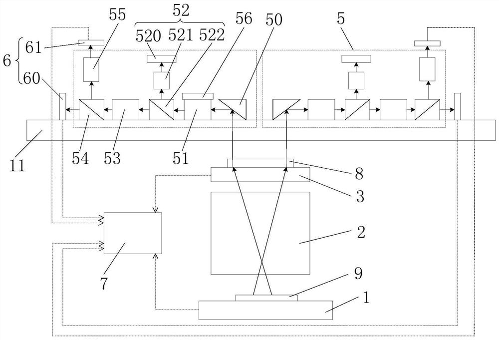
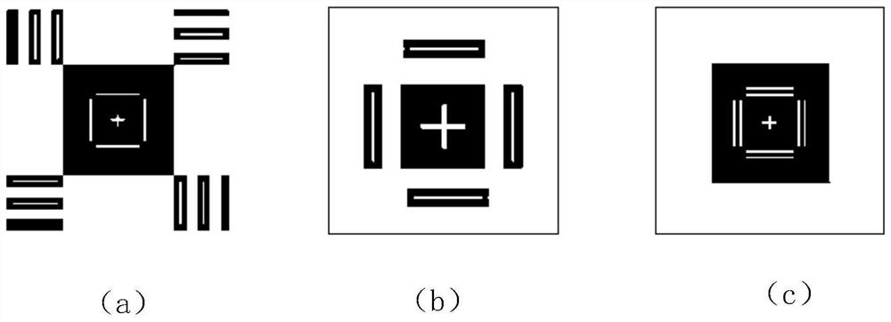
[0071] see Figure 1 to Figure 3 As shown, this embodiment provides a mask alignment system; figure 1 A schematic structural diagram of the mask alignment device provided in this embodiment, in which the path and direction of light transmission are shown by a solid line with arrows, and the path and direction of data transmission are shown by a dotted line with arrows, The imaging device is shown by the dashed box; figure 2 (a), (b), and (c) respectively show three types of registration marks applicable to the mask alignment device; image 3 for figure 2 Schematic diagram of the nesting principle of the third nesting mark in (c).

[0072] see Figure 1 to Figure 3 combine Figure 4 and Figure 6 As shown, the mask alignment system provided in this embodiment includes a data processing device 7, an image acquisition device 6, a workbench 1 for supporting a reference plate 9, a mask table 3 for supporting a reticle 8, and an imaging device and projection objective lens ...

Embodiment 2

[0107] Embodiment 2 provides a mask alignment method. This embodiment includes the mask alignment device in Embodiment 1. The technical features of the mask alignment device disclosed in Embodiment 1 are also applicable to this embodiment. Example 1 The technical features of the disclosed mask alignment device will not be described repeatedly.

[0108] Figure 4 Schematic diagram of the field of view under the alignment analysis step of the mask alignment method provided in this embodiment;

[0109] Figure 5 and Figure 6 Schematic diagrams of the principles of the two alignment analysis steps provided in this embodiment are respectively shown.

[0110] combine Figure 1 to Figure 3 and see Figure 4 to Figure 6 As shown, the mask alignment method provided in this embodiment specifically includes the following steps:

[0111] Projection imaging: place the reticle 8 on the mask table 3 so that the mask mark 80 on the reticle 8 falls into the object-side field of view of th...


PUM


Abstract

The invention relates to the technical field of photoetching equipment and process, concretely relates to a mask alignment system, a mask alignment method and photoetching equipment. The mask alignment system comprises a data processing device, an image acquisition device, a workbench, a mask table, an imaging device and a projection objective lens. The workbench and the mask table are arranged on the two sides of the projection objective lens respectively, a reference mark of the reference plate is projected on the mask plate in an inverted magnified image mode through the projection objective lens, the object side of the imaging device faces the mask plate, the image collecting device is arranged on the image side of the imaging device, and the data processing device can carry out image processing on shot images to determine the relative position relationship between the mask plate and the workbench. The mask alignment method and the photoetching equipment both adopt the mask alignment system. According to the mask alignment system, the mask alignment method and the photoetching equipment, the limitation on the measurement range is small, and various sleeving marks can be coped with.

Description

technical field [0001] The invention relates to the technical field of photolithography equipment and technology, in particular to a mask alignment system, a mask alignment method and photolithography equipment. Background technique [0002] Reticle is an indispensable part of photolithography process. The reticle bears the design pattern, and the light passes through it, projecting the design pattern on the photoresist. The performance of the mask directly determines the performance of the photolithography process. In a projection lithography machine, the reticle is used as an optical component between the illumination system and the projection lens, and it does not have direct contact with the wafer. The pattern on the reticle is shrunk by 4-10 times and projected on the wafer surface. [0003] The purpose of the photolithography process is to perfectly and accurately transfer the pattern on the reticle to the silicon wafer. The transfer manipulator transports the retic...

Claims


Application Information

Patent Timeline
Patent Type & Authority Applications(China)
IPC IPC(8): G03F9/00
CPCG03F9/7023G03F9/7088
Inventor 高爱梅武震李星辰
Owner BEIJING SEMICON EQUIP INST THE 45TH RES INST OF CETC
Learn More