Design method of high-lift centrifugal pump for conveying liquid easy to vaporize

A technology of vaporizing liquid and design method, which is applied in computer-aided design, design optimization/simulation, calculation, etc., can solve the problems of poor anti-cavitation performance, difficult rotor maintenance, and many impeller stages, etc., and achieves low cost, rotating Small inertia and the effect of expanding low cost

Active Publication Date: 2021-07-09
湖南天一奥星泵业有限公司
View PDF9 Cites 0 Cited by
  • Summary
  • Abstract
  • Description
  • Claims
  • Application Information

AI Technical Summary

Problems solved by technology

Overcome the attached figure 1 And attached figure 2 The two major defects of the high-lift VS6 pump were revealed (the number of impeller stages is large, and the maintenance of the rotor is very difficult; the mechanical seal needs to seal the outlet pressure of the pump), and it also overcomes the poor anti-cavitation performance of medium and large flow pitot tube pumps. Defects, the pitot tube pump mechanical seal only seals the inlet low pressure of the pump (this manual is attached) Figure 4 Part No. 4—Mechanical Seal of Pitot Tube Pump Sectional Drawing), that is, VS6 pump outlet low pressure with one impeller; Figure 4 , the outlet high pressure is sealed with two pieces of static item number 3 - the outer diameter of the horizontal section of the header and the item number 1 - the inner diameter of the coupling head, and the item number 2 - O-ring seal, the reliability is significantly improved

Method used


Image

  • Design method of high-lift centrifugal pump for conveying liquid easy to vaporize
  • Design method of high-lift centrifugal pump for conveying liquid easy to vaporize
  • Design method of high-lift centrifugal pump for conveying liquid easy to vaporize

Examples


Embodiment Construction

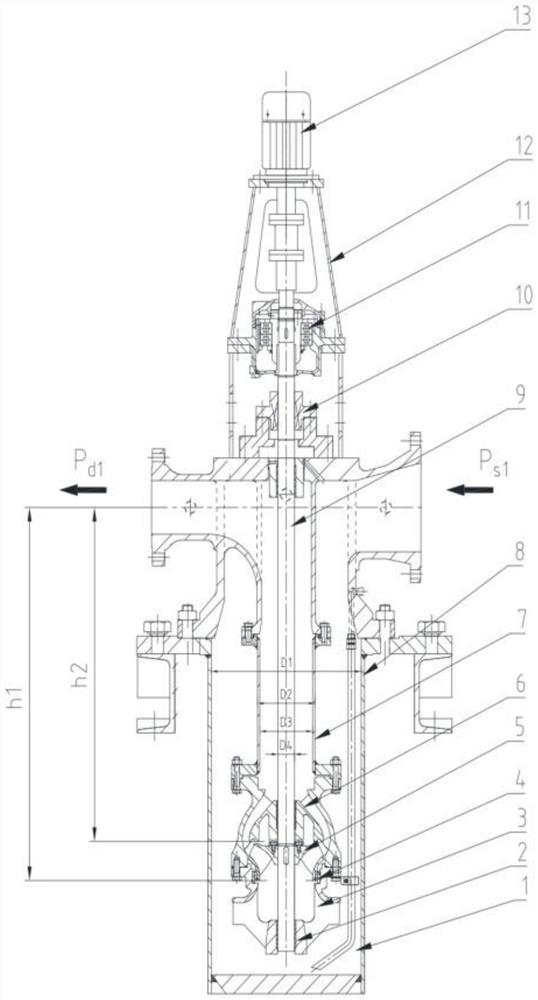
[0057] The following is an engineering example in the article "Engineering Example of Vertical Barrel Pump for Extremely Vaporizable Medium" searched on Baidu website and the attached manual. image 3 , to describe the design method of the present invention in detail, so as to facilitate the public to fully understand and realize the design method of the present invention.

[0058] An ethylene project of a Sinopec company, ethylene liquid delivery pump. Physical properties of liquid ethylene: temperature -35°C, specific gravity 0.449, vapor pressure 1.69MPa.A, viscosity 0.077cP. Pump parameters: flow rate 100m 3 / h, head 977m, speed 2980RPM, pressure at the center line of the pump inlet connection 1.694MPa.A, where the pressure of ethylene is only 0.004MPa higher than the vaporization pressure, ethylene is close to the vaporization state and there is a risk of cavitation, the first stage impeller must be Drop below the ground. Pump model TTMC80-230(B)×13, impeller 13 stages...


PUM


Abstract

The invention provides a design method of a high-lift centrifugal pump for conveying liquid easy to vaporize, and belongs to the field of centrifugal pumps. In order to overcome the technical defects that a rotor is difficult to overhaul and a mechanical seal needs to seal high pressure of a pump outlet of a high-lift centrifugal pump for conveying liquid easy to vaporize, the technical scheme is that a vertical barrel pump with one impeller is arranged underground, the depth of an inlet of the impeller under the ground needs to meet the anti-cavitation requirement, and an outlet of the pump is connected with an inlet of a pitot tube pump with one impeller on the ground. The design method comprises the steps: 1, calculating the depth h1 from the center line of an inlet connecting pipe of the vertical barrel pump to an impeller inlet through a formula 1; 2, increasing the pressure of an inlet of the pitot tube pump to prevent cavitation, and calculating the lift H1 of the vertical barrel pump through a formula 2; 3, calculating the lift H2 of the pitot tube pump, wherein the cross section area of the outer flow channel of the barrel is 4-4.5 times of the cross section area of the inner flow channel. The design method is further suitable for a unit formed by connecting an underground first-stage vertical barrel pump and an axial split type multi-stage centrifugal pump in series, wherein the axial split type multi-stage centrifugal pump is large in flow, high in rotating speed, large in NPSHr and easy to overhaul.

Description

technical field [0001] The invention belongs to a design method of a centrifugal pump, and in particular relates to a design method of a high-lift centrifugal pump for transporting easily vaporized liquid in an ethylene plant and an LNG plant. Background technique [0002] Ethylene is one of the most important basic raw materials in the petrochemical industry. The ethylene plant is the "leader" of the petrochemical industry. The liquid ethylene produced is transported to the storage tank for storage. Because the storage tank has a volume of tens of thousands of cubic meters, it can only be placed on the ground. The vertical barrel pump (hereinafter referred to as VS6 pump) is the key delivery pump of these two devices. Because the liquid ethylene and LNG at the inlet flange of the delivery pump are close to vaporization, the first stage impeller of the delivery pump can only be lowered to the ground , using the static pressure of the liquid column to increase the inlet press...

Claims


Application Information

Patent Timeline
Patent Type & Authority Applications(China)
IPC IPC(8): G06F30/17G06F30/28G06F113/08G06F119/14
CPCG06F30/17G06F30/28G06F2119/14G06F2113/08
Inventor 何备荒罗志冯少生罗幼如周季琪
Owner 湖南天一奥星泵业有限公司
Why Eureka
Try Eureka