Array antenna beam forming optimization method under non-convex multiple constraints

An array antenna and beamforming technology, which is applied in the field of array antenna beamforming optimization, can solve the problems that the convergence of the algorithm cannot be guaranteed theoretically, and achieve the goal of reducing the parameter adjustment process, low sidelobe level, and fast convergence speed Effect

Active Publication Date: 2021-07-09
UNIV OF ELECTRONICS SCI & TECH OF CHINA
View PDF13 Cites 5 Cited by
  • Summary
  • Abstract
  • Description
  • Claims
  • Application Information

AI Technical Summary

Problems solved by technology
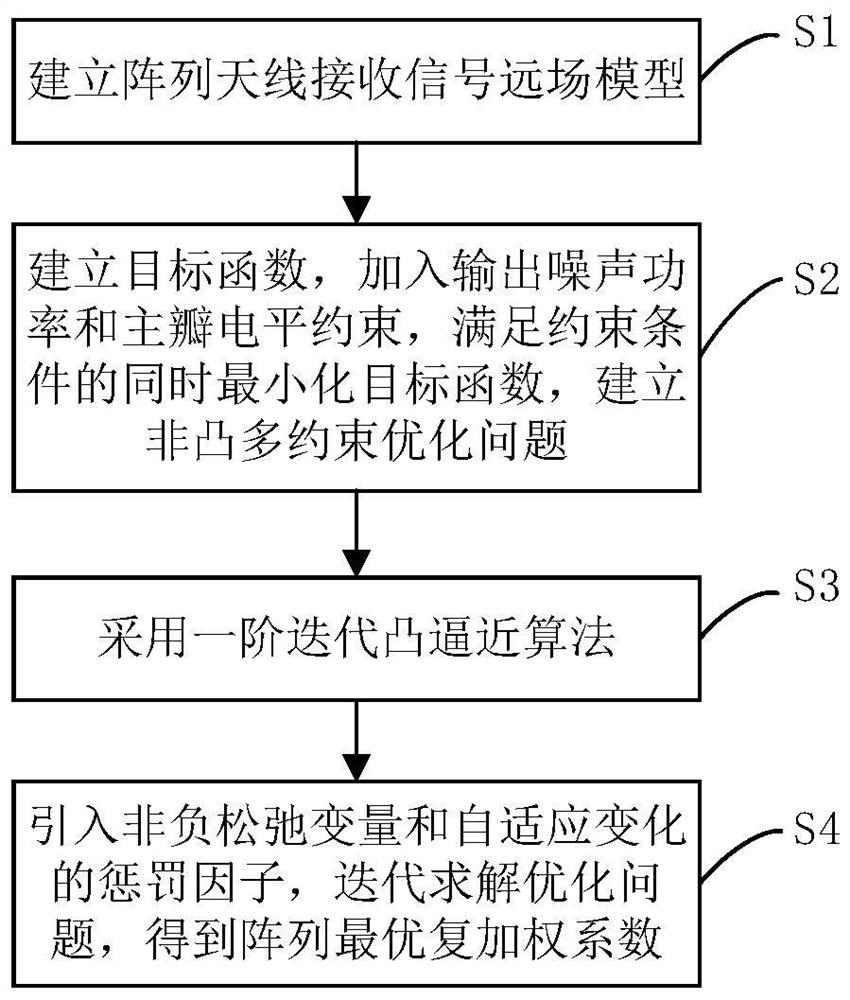
This algorithm can decompose the original non-convex optimization problem into multiple easy-to-solve sub-problems to iteratively solve, but it cannot theoretically guarantee the convergence of the algorithm, and requires human experience to adjust the penalty factor in the algorithm to obtain the desired beam shape

Method used


Image

  • Array antenna beam forming optimization method under non-convex multiple constraints
  • Array antenna beam forming optimization method under non-convex multiple constraints
  • Array antenna beam forming optimization method under non-convex multiple constraints

Examples


Embodiment 1

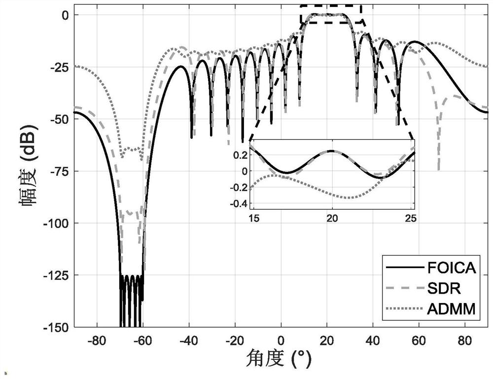
[0113] Embodiment 1: The number of isotropic uniform linear array (Isotropic Uniform Linear Array, IULA) array elements is N=20, the array element interval is half wavelength, and the array element radiation coefficient g n (θ)=1, the main lobe interval is θ m =[15°,25°], the side lobe area of ​​interest is θ s =[-70°,-60°], the upper and lower bounds of the main lobe level are constrained to α(θ m )=7.5dB,β(θ m )=8.0dB, penalty factor for adaptive change Maximum Tolerable Error gamma 1 =0.999,γ 2 = 1.001. Compare the FOICA algorithm and SDR, ADMM algorithm that the present invention adopts, wherein, the auxiliary variable parameter δ=3.95×10 in the SDR algorithm -3 , the maximum number of iterations set in the ADMM algorithm is K=2×10 4 , the penalty factors for the main lobe and side lobe regions are set to κ=50, ζ=10, respectively.

[0114] image 3 It is the normalized pattern corresponding to the optimized complex weighting coefficients obtained by using the t...

Embodiment 2

[0118] Embodiment 2: The number of array elements of nonisotropic linear random array (Nonisotropic Linear Random Array, NLRA) is N=20, and the main lobe considers an angle θ m = 20°, the sidelobe area of ​​interest is θ s =[-60°,-50°], the upper and lower bounds of the main lobe level are constrained to α(θ m )=-47.43dB,β(θ m )=-47.13dB, penalty factor for adaptive change Maximum Tolerable Error gamma 1 =0.999,γ 2 =1.001, the array element radiation coefficient function g n (θ) is expressed as:

[0119]

[0120] Among them, the radiation source direction and length parameter l involved n ,ξ n and array spacing d n parameter settings (d n , l n In units of wavelength λ, ξ n in degrees) as shown in Table 1.

[0121] Table 1

[0122] n d n (λ)

l n (λ)

ξ n (°)

n d n (λ)

l n (λ)

ξ n (°)

1 0.00 0.27 -2.70 11 4.92 0.22 4.32 2 0.46 0.29 4.36 12 5.42 0.28 2.63 3 0.94 0.22 1.83 13 5.88 0.22...


PUM


Abstract

The invention discloses an array antenna beam forming optimization method under non-convex multiple constraints. The method comprises the following steps: establishing a receiving signal far-field model for an array antenna beam forming problem; taking the side lobe level of the region of interest as a target function, considering main lobe interval shape control and output noise power requirements, adding main lobe interval level upper and lower bound limits and output noise power constraints, and establishing a non-convex optimization problem; therefore, the expected wave beam shape is obtained on the premise of not increasing the output noise power. According to the method, the non-convex constraint is approximated to be a convex upper bound function through the first-order iterative convex approximation algorithm, so that the non-convex multi-constraint optimization problem is approximated to be a convex optimization problem, and solving is easy; besides, the non-negative slack variable is introduced, so that the convergence speed of the algorithm is high, a self-adaptive change penalty factor is designed, and the parameter adjustment process of human experience is reduced; on the premise that it is guaranteed that the expected main lobe shape of a beam directional diagram is obtained, the obtained side lobe level of the region of interest is lower, and interference signals in the side lobe level direction are restrained.

Description

technical field [0001] The invention belongs to the technical field of array signal processing, and in particular relates to an array antenna beamforming optimization technology under non-convex multi-constraints. Background technique [0002] Array antennas are widely used in modern radar, sonar, wireless communication and other fields. The beamforming technology of the array antenna refers to obtaining the expected beam shape by designing the complex weighting coefficients of the spatial filter, so the optimization problem of the beamforming of the array antenna has been widely concerned and researched. In order to achieve effective reception of useful signals from the desired direction in space and suppression of interfering signals from other directions, the expected beam shapes include focused beams, wide main lobe beams, low side lobe beams, and side lobe zero beams, etc., so it is necessary The upper and lower bounds of the main lobe level and the upper bounds of the...

Claims


Application Information

Patent Timeline
Patent Type & Authority Applications(China)
IPC IPC(8): G06F30/20G06F111/04
CPCG06F30/20G06F2111/04
Inventor 崔国龙路晴辉刘瑞涛黄博伟余显祥张立东张雷王睿甲方学立孔令讲
Owner UNIV OF ELECTRONICS SCI & TECH OF CHINA
Why Eureka
Try Eureka